Product Preview
WM8983
In 2-wire mode the WM8983 has a fixed device address, 0011010.
RESETTING THE CHIP
The WM8983 can be reset by performing a write of any value to the software reset register (address
0h). This will cause all register values to be reset to their default values. In addition to this there is a
Power-On Reset (POR) circuit which ensures that the registers are initially set to default when the
device is powered up.
POWER SUPPLIES
The WM8983 requires four separate power supplies:
AVDD1 and AGND1: Analogue supply, powers all internal analogue functions and output drivers
LOUT1 and ROUT1. AVDD1 must be between 2.5V and 3.6V and has the most significant impact
on overall power consumption (except for power consumed in the headphones). Higher AVDD1 will
improve audio quality.
AVDD2 and AGND2: Output driver supplies, power LOUT2, ROUT2, OUT3 and OUT4. AVDD2 must
be between 2.5V and 5.5V. AVDD2 can be tied to AVDD1, but it requires separate layout and
decoupling capacitors to curb harmonic distortion.
DCVDD: Digital core supply, powers all digital functions except the audio and control interfaces.
DCVDD must be between 1.71V and 3.6V, and has no effect on audio quality. The return path for
DCVDD is DGND, which is shared with DBVDD.
DBVDD must be between 1.71V and 3.6V. DBVDD return path is through DGND.
It is possible to use the same supply voltage for all four supplies. However, digital and analogue
supplies should be routed and decoupled separately on the PCB to keep digital switching noise out
of the analogue signal paths.
POWER MANAGEMENT
SAVING POWER BY REDUCING OVERSAMPLING RATE
The default mode of operation of the ADC and DAC digital filters is in 64x oversampling mode.
Under the control of ADCOSR128 and DACOSR128 the oversampling rate may be doubled. 64x
oversampling results in a slight decrease in noise performance compared to 128x but lowers the
power consumption of the device.
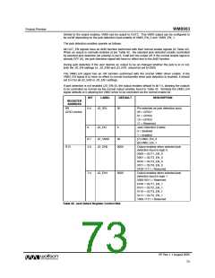
REGISTER
ADDRESS
BIT
LABEL
DEFAULT
DESCRIPTION
R10
3
3
DACOSR128
0
DAC oversample rate select
0 = 64x (lowest power)
1 = 128x (best SNR)
DAC control
R14
ADCOSR128
0
ADC oversample rate select
0 = 64x (lowest power)
1 = 128x (best SNR)
ADC control
Table 58 ADC and DAC Oversampling Rate Selection
VMID
The analogue cicruitry will not operate unless VMID is enabled. The impedance of the VMID resistor
string, together with the decoupling capacitor on the VMID pin will determine the startup time of the
VMID circuit.
REGISTER
ADDRESS
BIT
LABEL
DEFAULT
DESCRIPTION
R1
1:0
VMIDSEL
00
Reference string impedance to VMID pin
(Determines startup time):
Power
management 1
00 = off (250kΩ VMID to AGND1)
01 = 100kΩ total, 25kΩ impedance
10 = 500kΩ total, 125kΩ impedance
11 = 10kΩ total, 2.5kΩ impedance
Table 59 VMID Impedance Control
PP Rev 1.1 August 2005
75
w

 WOLFSON [ WOLFSON MICROELECTRONICS PLC ]