Product Preview
WM8983
REGISTER
ADDRESS
BIT
LABEL
MONO
DEFAULT
DESCRIPTION
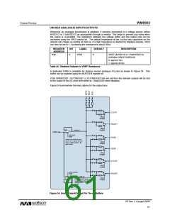
R4
0
0
Selects between stereo and mono
device operation:
Audio
Interface
Control
0 = Stereo device operation
1 = Mono device operation. Data
appears in ‘left’ phase of LRC.
1
2
ADCLRSWAP
DACLRSWAP
0
0
Controls whether ADC data appears in
‘right’ or ‘left’ phases of LRC clock:
0=ADC left data appear in ‘left’ phase of
LRC and right data in 'right' phase
1=ADC left data appear in ‘right’ phase
of LRC and right data in 'left' phase
Controls whether DAC data appears in
‘right’ or ‘left’ phases of LRC clock:
0=DAC left data appear in ‘left’ phase of
LRC and right data in 'right' phase
1=DAC left data appear in ‘right’ phase
of LRC and right data in 'left' phase
4:3
6:5
FMT
WL
10
10
Audio interface Data Format Select:
00=Right Justified
01=Left Justified
10=I2S format
11= DSP/PCM mode
Word length
00=16 bits
01=20 bits
10=24 bits
11=32 bits (see note)
LRC clock polarity
0=normal
7
8
0
LRP
0
0
0
1=inverted
BCP
BCLK polarity
0=normal
1=inverted
R5
LOOPBACK
Digital loopback function
0=No loopback
1=Loopback enabled, ADC data output
is fed directly into DAC data input.
Table 46 Audio Interface Control
Note: Right Justified Mode will only operate with a maximum of 24 bits. If 32-bit mode is selected the
device will operate in 24-bit mode.
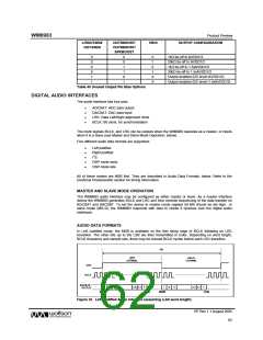
AUDIO INTERFACE CONTROL
The register bits controlling audio format, word length and master / slave mode are summarised
below.
Register bit MS selects audio interface operation in master or slave mode. In Master mode BCLK
and LRC are outputs. The frequencies of BCLK and LRC in master mode are controlled using
MCLKDIV; these clocks are divided down versions of PLL output clock (SYSCLK). The MCLKDIV
default setting provides a SYSCLK/256 division rate for the LRC output clock.
It is possible to divide down the BCLK rate using BCLKDIV; care must be taken in choosing the
correct BCLKDIV rate to maintain sufficient BCLK pulses per LRC period for the chosen data word
length. The BCLKDIV default setting provides a BCLK = SYSCLK clock.
PP Rev 1.1 August 2005
65
w

 WOLFSON [ WOLFSON MICROELECTRONICS PLC ]