WM8983
Product Preview
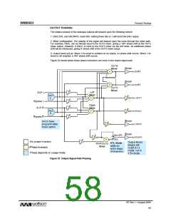
ENABLING THE OUTPUTS
Each analogue output of the WM8983 can be independently enabled or disabled. The analogue
mixer associated with each output has a separate enable bit. All outputs are disabled by default. To
save power, unused parts of the WM8983 should remain disabled.
Outputs can be enabled at any time, but it is not recommended to do so when BUFIO is disabled
(BUFIOEN=0), as this may cause pop noise (see “Power Management” and “Applications
Information” sections).
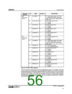
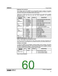
REGISTER
ADDRESS
BIT
LABEL
DEFAULT
DESCRIPTION
R1
2
BUFIOEN
0
0
0
0
0
0
0
Unused input/output bias buffer enable
OUT3 mixer enable
Power
Management
1
6
7
8
8
7
6
OUT3MIXEN
OUT4MIXEN
BUFDCOPEN
ROUT1EN
LOUT1EN
SLEEP
OUT4 mixer enable
Output stage 1.5xAVDD/2 driver enable
ROUT1 output enable
R2
Power
Management
2
LOUT1 output enable
0 = Normal device operation
1 = Supply current reduced in device
standby mode
R3
2
3
5
6
7
8
1
0
LMIXEN
0
0
0
0
0
0
0
0
Left mixer enable
Power
Management
3
RMIXEN
ROUT2EN
LOUT2EN
OUT3EN
OUT4EN
DELEN
Right mixer enable
ROUT2 output enable
LOUT2 output enable
OUT3 enable
OUT4 enable
2nd enable bit for L/ROUT1
R42
Output ctrl1
OUT1DEL
2 stage enable for L/ROUT1
Note: All “Enable” bits are 1 = ON, 0 = OFF
Table 42 Output Stages Power Management Control
OUT1DEL and OUT2DEL enable lower pop noise power-up option. See start–up sequences. (in 2
stage enable method, normal enable bit is set, followed shortly later by the delayed enable DELEN)
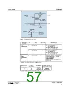
THERMAL SHUTDOWN
To protect the WM8983 from overheating a thermal shutdown circuit is included. If the device
temperature reaches approximately 1250C and the thermal shutdown circuit is enabled (TSDEN=1)
the L/ROUT2 amplifiers will be disabled. The thermal shutdown may also be configured to generate
an interrupt. See the GPIO and Interrupt Controller section for details.
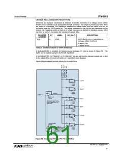
REGISTER
ADDRESS
BIT
LABEL
TSDEN
DEFAULT
DESCRIPTION
R49
Output Control
1
0
Thermal Shutdown Enable
0 : thermal shutdown disabled
1 : thermal shutdown enabled
Table 43 Thermal Shutdown
PP Rev 1.1 August 2005
60
w

 WOLFSON [ WOLFSON MICROELECTRONICS PLC ]