Product Preview
WM8983
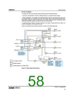
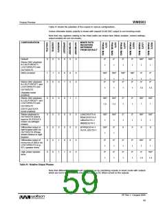
Table 41 shows the polarities of the outputs in various configurations.
Unless otherwise stated, polarity is shown with respect to left DAC output in non-inverting mode.
Note that only registers relating to the mixer paths are shown here (Mixer enables, volume settings,
output enables etc are not shown).
CONFIGURATION
MIXER PATH
REGISTERS
DIFFERENT
FROM DEFAULT
Default:
0
0
0
0
0
0
0°
1
0°
1
0°
1
0°
1
180°
1
180°
1
Stereo DAC playback
to LOUT1/ROUT1,
LOUT2/ROUT2 and
OUT4/OUT3
DACs inverted
1
0
1
0
0
0
0
1
0
0
0
0
180°
180°
180°
180°
0°
0°
1
1
1
1
1
1
Stereo DAC playback
to LOUT1/ROUT1 and
LOUT2/ROUT2 and
0°
0°
0°
0°
0°
0°
1
1
1
1
1.5
1.5
OUT4/OUT3
(Speaker boost
enabled)
Stereo DAC playback
to LOUT1/ROUT1 and
LOUT2/ROUT2 and
0
0
0
0
1
1
180°
1.5
180°
1.5
0°
1
0°
1
180°
1
180°
1
OUT4/OUT3
(OUT3 and OUT4
boost enabled)
Stereo playback to
OUT3/OUT4 (DACs
input to OUT3/OUT4
mixers via left/right
mixers)
0
0
0
0
0
0
0
0
0
0
0
0
LDAC2OUT3=0
RDAC2OUT4=0
LMIX2OUT3=1
RMIX2OUT4=1
180°
1
180°
1
0°
1
0°
1
180°
1
180°
1
Differential output of
right bypass path via
OUT3/OUT4 (Phase
shown relative to right
bypass)
BYPR2OUT4=1
OUT4_2OUT3=1
180°
1
0°
1
X
X
X
X
Differential output of
mono mix of DACs via
LOUT2/ROUT2 (e.g.
BTL speaker drive)
0
0
0
0
1
1
0
1
0
0
0
0
0°
1
0°
1
0°
1
0°
1
180°
1
0°
1
High power speaker
drive
0°
1
0°
1
0°
1
0°
1
0°
180°
1.5
1.5
Table 41 Relative Output Phases
Note that differential output should not be set up by combining outputs in boost mode with outputs
which are not in boost mode as this would cause a DC offset current on the outputs.
PP Rev 1.1 August 2005
59
w

 WOLFSON [ WOLFSON MICROELECTRONICS PLC ]