WM8904
Pre-Production
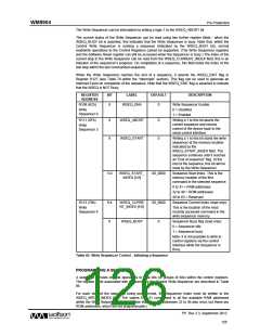
The Write Sequencer can be interrupted by writing a logic 1 to the WSEQ_ABORT bit.
The current status of the Write Sequencer can be read using two further register fields - when the
WSEQ_BUSY bit is asserted, this indicates that the Write Sequencer is busy. Note that, whilst the
Control Write Sequencer is running a sequence (indicated by the WSEQ_BUSY bit), normal
read/write operations to the Control Registers cannot be supported. (The Write Sequencer registers
and the Software Reset register can still be accessed when the Sequencer is busy.) The index of the
current step in the Write Sequencer can be read from the WSEQ_CURRENT_INDEX field; this is an
indicator of the sequencer’s progress. On completion of a sequence, this field holds the index of the
last step within the last commanded sequence.
When the Write Sequencer reaches the end of a sequence, it asserts the WSEQ_EINT flag in
Register R127 (see Table 79 within the “Interrupts” section). This flag can be used to generate an
Interrupt Event on completion of the sequence. Note that the WSEQ_EINT flag is asserted to indicate
that the WSEQ is NOT Busy.
REGISTER
ADDRESS
BIT
LABEL
DEFAULT
DESCRIPTION
R108 (6Ch)
Write Sequencer Enable.
0 = Disabled
8
WSEQ_ENA
0
Write
Sequencer 0
1 = Enabled
R111 (6Fh)
Writing a 1 to this bit aborts the
current sequence and returns
control of the device back to the
serial control interface.
9
8
WSEQ_ABORT
WSEQ_START
0
0
Write
Sequencer 3
Writing a 1 to this bit starts the write
sequencer at the memory location
indicated by the
WSEQ_START_INDEX field. The
sequence continues until it reaches
an “End of sequence” flag. At the
end of the sequence, this bit will be
reset by the Write Sequencer.
Sequence Start Index. This is the
memory location of the first
5:0
WSEQ_START_
INDEX [5:0]
00_0000
command in the selected sequence.
0 to 31 = RAM addresses
32 to 48 = ROM addresses
49 to 63 = Reserved
R112 (70h)
Sequence Current Index (read only):
9:4
0
WSEQ_CURRE
NT_INDEX [5:0]
00_0000
Write
Sequencer 4
This is the location of the most
recently accessed command in the
write sequencer memory.
Sequencer Busy flag (read only):
0 = Sequencer idle
WSEQ_BUSY
0
1 = Sequencer busy
Note: it is not possible to write to
control registers via the control
interface while the Sequencer is
Busy.
Table 85 Write Sequencer Control - Initiating a Sequence
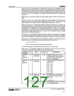
PROGRAMMING A SEQUENCE
A sequence consists of write operations to data bits (or groups of bits) within the control registers.
The register fields associated with programming the Control Write Sequencer are described in Table
86.
For each step of the sequence being programmed, the Sequencer Index must be written to the
WSEQ_WRITE_INDEX field. The values 0 to 31 correspond to all the available RAM addresses
within the Write Sequencer memory. (Note that memory addresses 32 to 48 also exist, but these are
ROM addresses, which are not programmable.)
PP, Rev 3.3, September 2012
126
w

 WOLFSON [ WOLFSON MICROELECTRONICS PLC ]