Pre-Production
WM8904
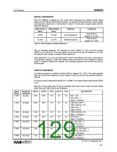
Read from 'Register Address'
MSByte Data 0 LSByte Data 0
S
Device ID
A
Register Address
A
Sr
Device ID
A
A
A
RW
RW
(0)
(1)
Read from 'Last Register Address+N-1'
MSByte Data N-1 LSByte Data N-1
Read from 'Last Register Address+N'
MSByte Data N LSByte Data N
A
A
A
A
A
P
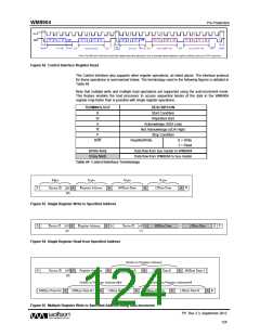
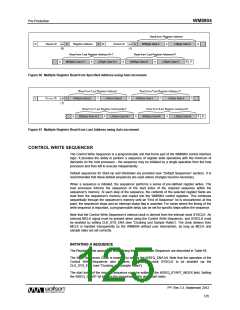
Figure 66 Multiple Register Read from Specified Address using Auto-increment
Figure 67 Multiple Register Read from Last Address using Auto-increment
CONTROL WRITE SEQUENCER
The Control Write Sequencer is a programmable unit that forms part of the WM8904 control interface
logic. It provides the ability to perform a sequence of register write operations with the minimum of
demands on the host processor - the sequence may be initiated by a single operation from the host
processor and then left to execute independently.
Default sequences for Start-Up and Shutdown are provided (see “Default Sequences” section). It is
recommended that these default sequences are used unless changes become necessary.
When a sequence is initiated, the sequencer performs a series of pre-defined register writes. The
host processor informs the sequencer of the start index of the required sequence within the
sequencer’s memory. At each step of the sequence, the contents of the selected register fields are
read from the sequencer’s memory and copied into the WM8904 control registers. This continues
sequentially through the sequencer’s memory until an “End of Sequence” bit is encountered; at this
point, the sequencer stops and an Interrupt status flag is asserted. For cases where the timing of the
write sequence is important, a programmable delay can be set for specific steps within the sequence.
Note that the Control Write Sequencer’s internal clock is derived from the internal clock SYSCLK. An
external MCLK signal must be present when using the Control Write Sequencer, and SYSCLK must
be enabled by setting CLK_SYS_ENA (see “Clocking and Sample Rates”). The clock division from
MCLK is handled transparently by the WM8904 without user intervention, as long as MCLK and
sample rates are set correctly.
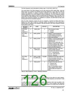
INITIATING A SEQUENCE
The Register fields associated with running the Control Write Sequencer are described in Table 85.
The Write Sequencer Clock is enabled by setting the WSEQ_ENA bit. Note that the operation of the
Control Write Sequencer also requires the internal clock SYSCLK to be enabled via the
CLK_SYS_ENA (see “Clocking and Sample Rates”).
The start index of the required sequence must be written to the WSEQ_START_INDEX field. Setting
the WSEQ_START bit initiates the sequencer at the given start index.
PP, Rev 3.3, September 2012
125
w

 WOLFSON [ WOLFSON MICROELECTRONICS PLC ]