WM8904
Pre-Production
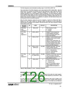
DESCRIPTION
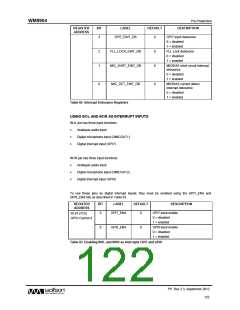
REGISTER
ADDRESS
BIT
LABEL
DEFAULT
GPI7 input debounce
0 = disabled
3
GPI7_EINT_DB
0
1 = enabled
FLL Lock debounce
0 = disabled
2
1
FLL_LOCK_EINT_DB
MIC_SHRT_EINT_DB
0
0
1 = enabled
MICBIAS short circuit interrupt
debounce
0 = disabled
1 = enabled
MICBIAS current detect
interrupt debounce
0
MIC_DET_EINT_DB
0
0 = disabled
1 = enabled
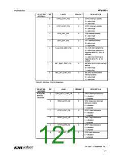
Table 82 Interrupt Debounce Registers
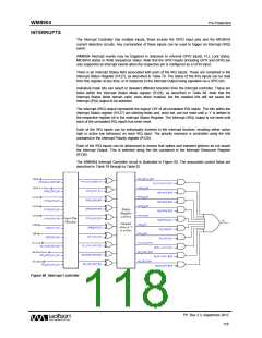
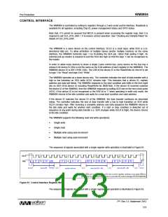
USING IN1L AND IN1R AS INTERRUPT INPUTS
IN1L pin has three input functions.
Analogue audio input
Digital microphone input (DMICDAT1)
Digital interrupt input (GPI7)
IN1R pin has three input functions.
Analogue audio input
Digital microphone input (DMICDAT2)
Digital interrupt input (GPI8)
To use these pins as digital interrupt inputs, they must be enabled using the GPI7_ENA and
GPI8_ENA bits as described in Table 83.
REGISTER
ADDRESS
BIT
LABEL
DEFAULT
DESCRIPTION
GPI7 input enable
9
GPI7_ENA
0
R124 (7Ch)
0 = disabled
1 = enabled
GPIO Control 4
GPI8 input enable
0 = disabled
1 = enabled
8
GPI8_ENA
0
Table 83 Enabling IN1L and IN1R as Interrupts GPI7 and GPI8
PP, Rev 3.3, September 2012
122
w

 WOLFSON [ WOLFSON MICROELECTRONICS PLC ]