WM8805
Production Data
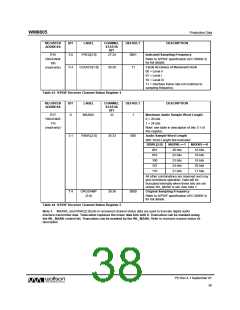
REGISTER
ADDRESS
BIT
LABEL
CHANNEL
STATUS
BIT
DEFAULT
DESCRIPTION
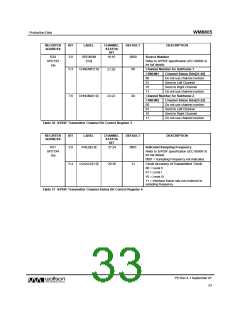
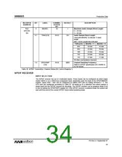
R22
SPDTX5
16h
0
MAXWL
32
1
Maximum Audio Sample Word Length
0 = 20 bits
1 = 24 bits
3:1
TXWL[2:0]
35:33
101
Audio Sample Word Length
Used with MAXWL to indicate Tx word
length
000 = Word Length Not Indicated
TXWL[2:0]
001
MAXWL==1
20 bits
MAXWL==0
16 bits
010
22 bits
18 bits
100
23 bits
19 bits
101
24 bits
20 bits
110
21 bits
17 bits
All other combinations reserved
7:4
ORGSAMP
[3:0]
39:36
0000
Original Sampling Frequency
Refer to S/PDIF specification (IEC 60958-3)
for full details.
Table 38 S/PDIF Transmitter Channel Status Bit Control Register 5
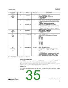
S/PDIF RECEIVER
INPUT SELECTION
The S/PDIF receiver has up to 8 dedicated inputs. These inputs can be configured as either single
ended CMOS or as a 500mVp-p comparator input, depending upon the state of the SPDIFINMODE
register. Inputs RX4 – RX7 can be configured as CMOS GPO pins by setting SPDGPO = 1. The
GPO pins are configured according to Table 52. All inputs go to a selection mux which passes a
single input into the S/PDIF receiver for decoding. The S/PDIF receiver can be powered down if not
in use by setting the SPDIFRXPD register bit. If the S/PDIF receiver is powered down the system will
wait until then end of the current S/PDIF frame before powering down.
PD Rev 4.1 September 07
34
w

 WOLFSON [ WOLFSON MICROELECTRONICS PLC ]