Production Data
WM8805
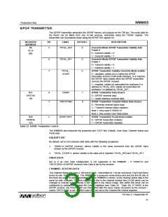
S/PDIF TRANSMITTER
The S/PDIF transmitter generates the S/PDIF frames, and outputs on the TX0 pin. The audio data for
the frame can be taken from one of two sources, selectable using the TXSRC register. The
transmitter can be powered down using the SPDIFTXD register bit.
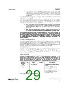
REGISTER
ADDRESS
BIT
LABEL
DEFAULT
DESCRIPTION
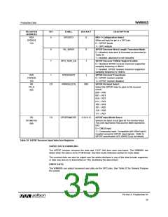
R6
PLL4
06h
5
TXVAL_SF0
0
Overwrite Mode S/PDIF Transmitter Validity Sub-
Frame 0
0 = transmit validity = 0
1 = transmit validity = 1
6
7
TXVAL_SF1
0
0
Overwrite Mode S/PDIF Transmitter Validity Sub-
Frame 1
0 = transmit validity = 0
1 = transmit validity = 1
TXVAL_
OVWR
S/PDIF Transmitter Validity Overwrite Mode Enable
0 = disabled, validity bit is 0 when the S/PDIF
transmitter sources PCM audio interface, or it matches
the S/PDIF input validity when the S/PDIF transmitter
sources the S/PDIF receiver.
1 = enabled, validity bit transmitted for subframe 0 is
defined by TXVAL_SF0, validity bit transmitted for
subframe 1 is defined by TXVAL_SF1.
R21
SPDTX4
15h
6
7
TXSRC
1
0
S/PDIF Transmitter Data Source
0 = S/PDIF received data.
1 = Audio Interface received data
S/PDIF Transmitter Channel Status Data Source
0 = Received channel status data
1 = Transmit channel status registers
Note 1: Only used if TXSRC=0
TXSTATSRC
Note 2: See section User Data below
S/PDIF Transmitter Powerdown Enable
0 = S/PDIF transmitter enabled
R30
PWRDN
1Eh
2
SPDIFTXPD
1
1 = S/PDIF transmitter disabled
Table 33 S/PDIF Transmitter Control
The WM8805 also transmits the preamble and VUCP bits (Validity, User Data, Channel Status and
Parity bits).
VALIDITY BIT
By default, set to 0 (to indicate valid data) with the following exceptions:
1. TXSRC=0 (S/PDIF receiver), where Validity is the value recovered from the S/PDIF input
stream by the S/PDIF receiver.
2. TXVAL_OVWR=1, where Validity is the value set in registers TXVAL_SF0 and TXVAL_SF1.
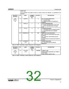
USER DATA
Set to 0 as User Data configuration is not supported in the WM8805 – if TXSRC=0 and
TXSTATSRC=0 (S/PDIF receiver) User Data is set by the receiver.
CHANNEL STATUS DATA
The Channel Status bits form a 192-frame block - transmitted at 1 bit per sub-frame. Each sub-frame
forms its own 192-frame block. The WM8805 is a consumer mode device and only the first 40 bits of
the block are used. All data transmitted from the WM8805 is stereo, so the channel status data is the
same for both channels. The only exception to this is the channel number bits (23:20) which can be
changed to indicate if the channel is left or right in the stereo image. Bits within this block can be
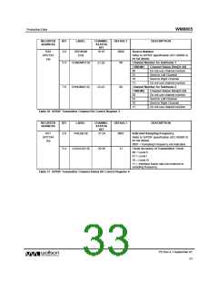
configured by setting the Channel Bit Control registers (see Table 34 - Table 38). If TXSRC is the
S/PDIF receiver, the Channel bits are transmitted with the same values recovered by the receiver –
unless TXSTATSRC is set, in which case they are set by the Channel Bit Control registers.
PD Rev 4.1 September 07
31
w

 WOLFSON [ WOLFSON MICROELECTRONICS PLC ]