WM8805
Production Data
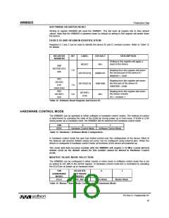
SOFTWARE REGISTER RESET
Writing to register 0000000 will reset the WM8805. This will reset all register bits to their default
values. Note that the WM8805 is powered down by default so writing to this register will power down
the device.
DEVICE ID AND REVISION IDENTIFICATION
Registers 0,1 and 2 can be read to identify the device ID and IC revision number. Refer to Table 12
for details.
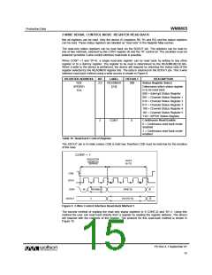
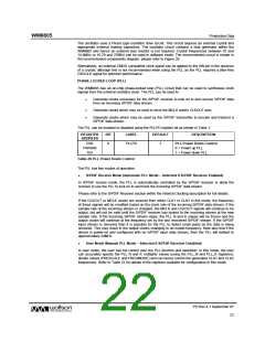
REGISTER
ADDRESS
BIT
LABEL
DEFAULT
DESCRIPTION
Writing to this register will apply a
reset to the device.
RESET
N/A
R00
RST/DEVID1
00h
7:0
Reading from this register will return
the second part of the device ID
DEVID1[7:0]
DEVID2[7:0]
00000101
10001000
N/A
00000101 = 0x05
R01
DEVID2
01h
Reading from this register will return
the first part of the device ID
7:0
3:0
10001000 = 0x88
(read only)
R02
Reading from this register will return
the device revision.
DEVREV
[3:0]
DEVREV
02h
0x1 = revision 1
Table 12 Software Reset Register and Device ID
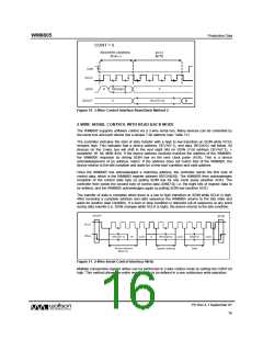
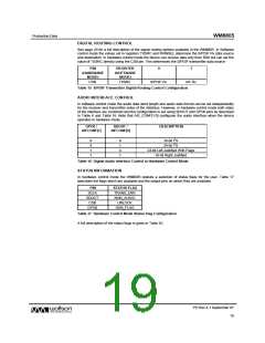
HARDWARE CONTROL MODE
The WM8805 can be operated in either software or hardware control modes. The method of control
is determined by sampling the state of the SDIN pin during power up or hard reset. If SDIN is LOW
during power up or hardware reset, the WM8805 will be switched into hardware control mode.
PIN
0
1
SDIN
Hardware Control Mode
Software Control Mode
Table 13 Hardware / Software Mode Configuration
In hardware control mode the user has limited control over the configuration of the device. Most of
the features will assume default values but some can be configured using external pins. When the
device is configured in hardware control mode, all functions of the device are powered up.
The clock and data recovery module with the WM8805 will require a 12 MHz crystal derived
master clock as the default values for this module cannot be altered in Hardware Control
mode.
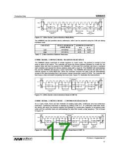
MASTER / SLAVE MODE SELECTION
The WM8805 can be configured in either master or slave mode In software control mode this is set
by writing to AIF_MS in the AIFRX register. In hardware control mode this is controlled by sampling
the SCLK pin on power up or hardware reset.
PIN
REGISTER
0
1
(HARDWARE
MODE)
(SOFTWARE
MODE)
SCLK
AIF_MS
Slave Mode
Master Mode
Table 14 Master / Slave Mode Configuration in Hardware Mode
PD Rev 4.1 September 07
18
w

 WOLFSON [ WOLFSON MICROELECTRONICS PLC ]