WM8774
Product Preview
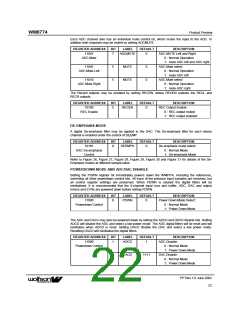
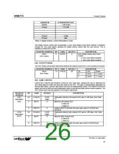
Each ADC channel also has an individual mute control bit, which mutes the input to the ADC. In
addition both channels may be muted by setting ADCMUTE.
REGISTER ADDRESS
11001
BIT
LABEL
DEFAULT
DESCRIPTION
ADC MUTE Left and Right
0 : Normal Operation
1: mute ADC left and ADC right
ADC Mute select
7
ADCMUTE
0
ADC Mute
11001
5
5
MUTE
MUTE
0
0
ADC Mute Left
0 : Normal Operation
1: mute ADC left
11010
ADC Mute select
ADC Mute Right
0 : Normal Operation
1: mute ADC right
The Record outputs may be enabled by setting RECEN, where RECEN enables the RECL and
RECR outputs.
REGISTER ADDRESS
10100
BIT
LABEL
DEFAULT
DESCRIPTION
REC Output Enable
5
RECEN
0
REC Enable
0 : REC output muted
1: REC output enabled
DE-EMPHASIS MODE
A digital De-emphasis filter may be applied to the DAC. The De-emphasis filter for each stereo
channel is enabled under the control of DEEMP.
REGISTER ADDRESS
10101
BIT
LABEL
DEFAULT
DESCRIPTION
De-emphasis mode select:
0 : Normal Mode
0
DEEMPH
0
DAC De-emphasis
Control
1: De-emphasis Mode
Refer to Figure 26, Figure 27, Figure 28, Figure 29, Figure 30 and Figure 31 for details of the De-
Emphasis modes at different sample rates.
POWERDOWN MODE AND ADC/DAC DISABLE
Setting the PDWN register bit immediately powers down the WM8774, including the references,
overriding all other powerdown control bits. All trace of the previous input samples are removed, but
all control register settings are preserved. When PDWN is cleared the digital filters will be
reinitialised. It is recommended that the 8-channel input mux and buffer, ADC, DAC and output
mixers and EVRs are powered down before setting PDWN.
REGISTER ADDRESS
11000
BIT
LABEL
DEFAULT
DESCRIPTION
Power Down Mode Select:
0 : Normal Mode
0
PDWN
0
Powerdown Control
1: Power Down Mode
The ADC and DACs may also be powered down by setting the ADCD and DACD disable bits. Setting
ADCD will disable the ADC and select a low power mode. The ADC digital filters will be reset and will
reinitialise when ADCD is reset. Setting DACD disable the DAC and select a low power mode.
Resetting DACD will reinitialise the digital filters.
REGISTER ADDRESS
11000
BIT
LABEL
DEFAULT
DESCRIPTION
ADC Disable:
0 : Normal Mode
1: Power Down Mode
DAC Disable:
1
ADCD
1
Powerdown Control
2
DACD
1111
0 : Normal Mode
1: Power Down Mode
PP Rev 1.0 June 2002
22
ꢀꢀ

 WOLFSON [ WOLFSON MICROELECTRONICS PLC ]