Product Preview
WM8774
BIT
LABEL
DEFAULT
DESCRIPTION
10011
3
TOD
0
DAC Analogue Zero cross detect
timeout disable
Timeout Clock Disable
0 : Timeout enabled
1: Timeout disabled
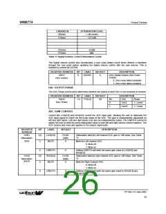
DAC ANALOGUE OUTPUT ATTENUATION
Register bits LA and RA control the left and right channel attenuation of DAC. Register bits MASTA
can be used to control attenuation of both channels.
Table 8 shows how the attenuation levels are selected from the 7-bit words.
L/RA[6:0]
00(hex)
:
ATTENUATION LEVEL
-∞dB (mute)
:
-∞dB (mute)
-100dB
:
1A(hex)
1B(hex)
:
7D(hex)
7E(hex)
7F(hex)
-2dB
-1dB
0dB
Table 10 Analogue Volume Control Attenuation Levels
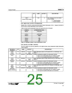
DAC DIGITAL VOLUME CONTROL
The DAC volume may also be adjusted in the digital domain using independent digital attenuation
control registers
REGISTER
ADDRESS
BIT
LABEL
DEFAULT
DESCRIPTION
01001
7:0
LDA[7:0]
11111111
(0dB)
Digital Attenuation data for Left channel DACL in 0.5dB steps. See
Table 11
Digital
Attenuation
8
UPDATE
Not latched
Controls simultaneous update of all Attenuation Latches
0: Store LDA in intermediate latch (no change to output)
1: Store LDA and update attenuation on all channels
DACL
01010
7:0
8
RDA[6:0]
UPDATE
11111111
(0dB)
Digital Attenuation data for Right channel DACR in 0.5dB steps. See
Table 11
Digital
Attenuation
DACR
Not latched
Controls simultaneous update of all Attenuation Latches
0: Store RDA in intermediate latch (no change to output)
1: Store RDA and update attenuation on all channels.
10001
7:0
8
ASTDA[7:0]
UPDATE
11111111
(0dB)
Digital Attenuation data for both DAC channels in 0.5dB steps. See
Table 11
Master
Digital
Attenuation
Not latched
Controls simultaneous update of all Attenuation Latches
0: Store gain in intermediate latch (no change to output)
1: Store gain and update attenuation on all channels.
(both channels)
PP Rev 1.0 June 2002
25
ꢀꢀ

 WOLFSON [ WOLFSON MICROELECTRONICS PLC ]