WM8774
Product Preview
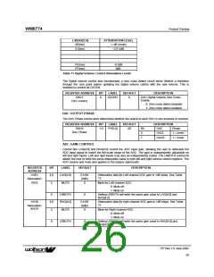
L/RDAX[7:0]
ATTENUATION LEVEL
00(hex)
-∞ dB (mute)
01(hex)
-127.5dB
:
:
:
:
:
:
FE(hex)
FF(hex)
-0.5dB
0dB
Table 11 Digital Volume Control Attenuation Levels
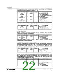
The Digital volume control also incorporates a zero cross detect circuit which detects a transition
through the zero point before updating the digital volume control with the new volume. This is
enabled by control bit DZCEN.
REGISTER ADDRESS
10011
BIT
LABEL
DEFAULT
DESCRIPTION
0
DZCEN
0
DAC Digital Volume Zero Cross
Enable:
DAC Control
0: Zero cross detect disabled
1: Zero cross detect enabled
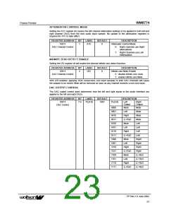
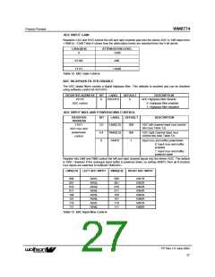
DAC OUTPUT PHASE
The DAC Phase control word determines whether the output of each DAC is non-inverted or inverted
REGISTER ADDRESS
10010
BIT
LABEL
DEFAULT
DESCRIPTION
1:0
PH[1:0]
00
Bit
0
DAC
Phase
DAC Phase
DACL
1 = invert
1 = invert
1
DACR
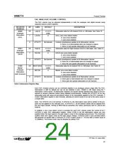
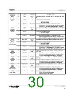
ADC GAIN CONTROL
Control bits LAG[4:0] and RAG[4:0] control the ADC input gain, allowing the user to attenuate the
ADC input signal to match the full-scale range of the ADC. The gain is independently adjustable on
left and right inputs. Left and right inputs may also be independently muted. The LRBOTH control bit
allows the user to write the same attenuation value to both left and right volume control registers. The
ADC volume and mute also applies to the bypass signal path.
REGISTER
ADDRESS
BIT
LABEL
DEFAULT
DESCRIPTION
11001
Attenuation
ADCL
4:0
LAG[4:0]
01100
(0dB)
0
Attenuation data for Left channel ADC gain in 1dB steps. See Table
12
5
MUTE
Mute for Left channel ADC:
0: Mute off
1: Mute on
6
LRBOTH
RAG[4:0]
0
Setting LRBOTH will write the same gain value to LAG[4:0] and
RAG[4:0]
11010
4:0
01100
(0dB)
0
Attenuation data for right channel ADC gain in 1dB steps. See Table
12
Attenuation
ADCR
5
6
MUTE
Mute for Right channel ADC:
0: Mute off
1: Mute on
LRBOTH
0
Setting LRBOTH will write the same gain value to RAG[4:0] and
LAG[4:0]
PP Rev 1.0 June 2002
26
ꢀꢀ

 WOLFSON [ WOLFSON MICROELECTRONICS PLC ]