Product Preview
WM8774
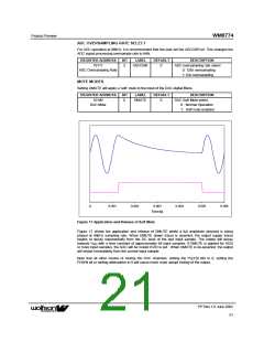
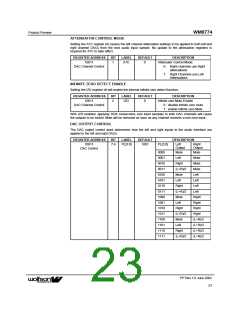
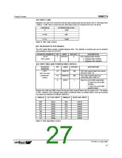
ATTENUATOR CONTROL MODE
Setting the ATC register bit causes the left channel attenuation settings to be applied to both left and
right channel DACs from the next audio input sample. No update to the attenuation registers is
required for ATC to take effect.
REGISTER ADDRESS
10011
BIT
LABEL
DEFAULT
DESCRIPTION
1
ATC
0
Attenuator Control Mode:
DAC Channel Control
0 : Right channels use Right
attenuations
1: Right Channels use Left
Attenuations
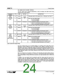
INFINITE ZERO DETECT ENABLE
Setting the IZD register bit will enable the internal infinite zero detect function:
REGISTER ADDRESS
10011
BIT
LABEL
DEFAULT
DESCRIPTION
Infinite zero Mute Enable
0 : disable infinite zero mute
1: enable infinite zero Mute
2
IZD
0
DAC Channel Control
With IZD enabled, applying 1024 consecutive zero input samples to both DAC channels will cause
the outputs to be muted. Mute will be removed as soon as any channel receives a non-zero input.
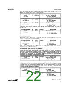
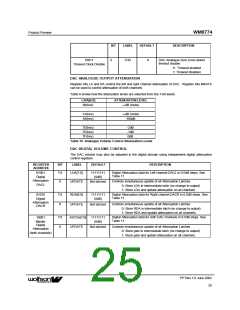
DAC OUTPUT CONTROL
The DAC output control word determines how the left and right inputs to the audio Interface are
applied to the left and right DACs:
REGISTER ADDRESS
10011
BIT
LABEL
DEFAULT
DESCRIPTION
7:4
PL[3:0]
1001
PL[3:0]
Left
Right
Output
Output
DAC Control
0000
0001
0010
0011
0100
0101
0110
0111
1000
1001
1010
1011
1100
1101
1110
1111
Mute
Left
Mute
Mute
Mute
Mute
Left
Right
(L+R)/2
Mute
Left
Left
Right
(L+R)/2
Mute
Left
Left
Left
Right
Right
Right
Right
(L+R)/2
(L+R)/2
(L+R)/2
(L+R)/2
Right
(L+R)/2
Mute
Left
Right
(L+R)/2
PP Rev 1.0 June 2002
23
ꢀꢀ

 WOLFSON [ WOLFSON MICROELECTRONICS PLC ]