WM8774
Product Preview
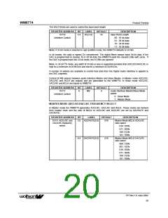
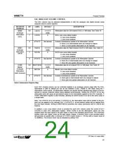
The WL[1:0] bits are used to control the input word length.
REGISTER ADDRESS
10110
BIT
LABEL
DEFAULT
DESCRIPTION
Input Word Length
5:4
WL[1:0]
10
Interface Control
00 : 16 bit data
01: 20 bit data
10: 24 bit data
11: 32 bit data
Note: If 32-bit mode is selected in right justified mode, the WM8774 defaults to 24 bits.
In all modes, the data is signed 2’s complement. The digital filters always input 24-bit data. If the
DAC is programmed to receive 16 or 20 bit data, the WM8774 pads the unused LSBs with zeros. If
the DAC is programmed into 32 bit mode, the 8 LSBs are ignored.
Note: In 24 bit I2S mode, any width of 24 bits or less is supported provided that ADCLRC/DACLRC is
high for a minimum of 24 BCLKs and low for a minimum of 24 BCLKs.
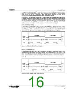
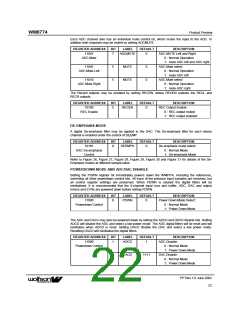
A number of options are available to control how data from the Digital Audio Interface is applied to
the DAC channels.
Control bit MS selects between audio interface Master and Slave Modes. In Master mode ADCLRC,
DACLRC and BCLK are outputs and are generated by the WM8774. In Slave mode ADCLRC,
DACLRC and BCLK are inputs to WM8774.
REGISTER ADDRESS
10111
BIT
LABEL
DEFAULT
DESCRIPTION
8
MS
0
Audio Interface Master/Slave Mode
select:
Interface Control
0 : Slave Mode
1: Master Mode
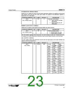
MASTER MODE ADCLRC/DACLRC FREQUENCY SELECT
In Master mode the WM8774 generates ADCLRC, DACLRC and BCLK. These clocks are derived
from master clock and the ratio of MCLK to ADCLRC and DACLRC are set by ADCRATE and
DACRATE.
REGISTER ADDRESS
BIT
LABEL
DEFAULT
DESCRIPTION
10111 ADCLRC and
DACLRC frequency
select
2:0 ADCRATE[2:0]
010
Master Mode MCLK:ADCLRC
ratio select:
010: 256fs
011: 384fs
100: 512fs
101: 768fs
6:4 DACRATE[2:0]
010
Master Mode MCLK:DACLRC
ratio select:
000: 128fs
001: 192fs
010: 256fs
011: 384fs
100: 512fs
101: 768fs
PP Rev 1.0 June 2002
20
ꢀꢀ

 WOLFSON [ WOLFSON MICROELECTRONICS PLC ]