Production Data
WM8352
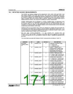
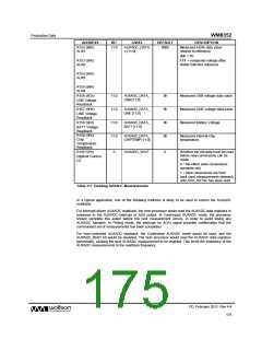
ADDRESS
R152 (98h)
AUX1
BIT
LABEL
DEFAULT
DESCRIPTION
11:0
AUXADC_DATA
n [11:0]
000h
Measured AUXn data value
relative to reference:
000 = 0V
R153 (99h)
AUX2
FFF = measured voltage after
divide matches reference
R154 (9Ah)
AUX3
R155 (9Bh)
AUX4
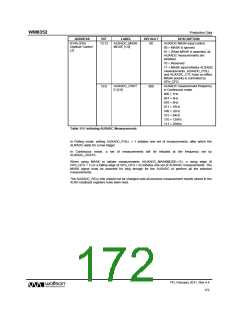
R156 (9Ch)
11:0
11:0
11:0
11:0
AUXADC_DATA_
USB [11:0]
0h
0h
0h
0h
Measured USB voltage data value.
Measured LINE voltage data value
Measured Battery Voltage
USB Voltage
Readback
R157 (9Dh)
AUXADC_DATA_
LINE [11:0]
LINE Voltage
Readback
R158 (9Eh)
AUXADC_DATA_
BATT [11:0]
BATT Voltage
Readback
R159 (9Fh)
Chip
AUXADC_DATA_
CHIPTEMP [11:0]
Measured Internal chip
temperature
Temperature
Readback
R145 (91h)
0
AUXADC_WAIT
0
Whether the old data must be read
before new conversions can be
made
Digitizer Control
(2)
0 = No effect (new conversions
overwrite old)
1 = New conversions are held
back (and measurements delayed)
until AUX_DATAn has been read.
Table 117 Reading AUXADC Measurements
In a typical application, one of the following methods is likely to be used to control the AUXADC
readback:
For interrupt-driven AUXADC readback, the host processor would read the AUXADC data registers in
response to the AUXADC Interrupt or ADA output. In Continuous AUXADC mode, the processor
should complete this action before the next measurement occurs, in order to avoid losing any
AUXADC samples. In Polling mode, the interrupt (or ADA) signal provides confirmation that the
commanded set of measurements has been completed.
For host-controlled AUXADC readback, the Continuous AUXADC mode would be used, and the
AUXADC_WAIT bit would be asserted. The host processor would read the AUXADC data registers
periodically, causing the next AUXADC measurement to be enabled. This limits the frequency of the
AUXADC measurements to the readback frequency.
PD, February 2011, Rev 4.4
175
w

 WOLFSON [ WOLFSON MICROELECTRONICS PLC ]