Production Data
WM8352
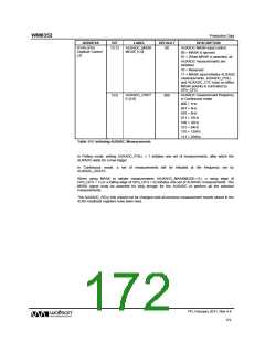
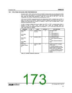
19.3 VOLTAGE SCALING AND REFERENCES
For inputs AUX1, AUX2, AUX3 and AUX4, the AUXADC measurements may be referenced to either
VRTC or VREF (see Section 21). The selected reference can be selected independently for each
input, using the control fields described in Table 116. In the case of USB, BATT, LINE and
Temperature, the AUXADC measurements are referenced to VRTC.
In the case of AUXADC measurements which are referenced to VREF, a buffered copy of VREF is
used as an input to the AUXADC. Setting the AUXADC_RBMODE field allows this buffer to be
enabled at all times when the AUXADC is enabled, or else to only be enabled when a VREF-
referenced measurement is made.
In order to measure voltages that may be higher than VRTC or VREF, a programmable divider is
provided on each of AUX1, AUX2, AUX3 and AUX4. These are controlled using the
AUXADC_SCALEn bits, allowing the inputs to be divided by 1, 2 or 4. In the case of USB, BATT and
LINE, a fixed ‘divide by 2’ applies.
ADDRESS
R152 (98h)
BIT
LABEL
DEFAULT
DESCRIPTION
AUXn input select
14:13
AUXADC_SCAL
11
AUX1
En [1:0]
00 = Off
01 = Input divided by 1
10 = Input divided by 2
11 = Input divided by 4
AUXn reference select
R153 (99h)
AUX2
12
AUXADC_REFn
1
R154 (9Ah)
AUX3
0 = AUXn measured relative to
VRTC
1 = AUXn measured relative to
VREF
R155 (9Bh)
AUX4
R145 (91h)
1
AUXADC_RBM
ODE
Enable for AUXADC bandgap
(VREF) buffer.
1
Digitizer Control
(2)
0 = AUXADC REFBUF is only
enabled during conversions that
use the VREF as a reference
1 = AUXADC REFBUF is always
enabled when the AUXADC is
enabled
Table 116 AUXADC Reference Selection
PD, February 2011, Rev 4.4
173
w

 WOLFSON [ WOLFSON MICROELECTRONICS PLC ]