WM8352
Production Data
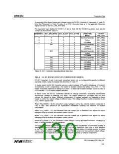
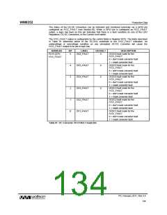
A summary of the Mode Control and Voltage Control for DC-DC Converter 1 is provided in Table 76.
Note that “Hibernate” in Table 76 refers to a GPIO Hibernate input or to the applicable Hibernate
signal selected by the DC1_HIB_TRIG field.
The equivalent logic applies for DC-DC 3, 4 and 6. Note that the DC-DC Converters must also be
enabled as described in Table 71.
HIBERNATE DC1_HIB_MODE DC1_SLEEP DC1_ACTIVE
OPERATING
MODE
OUTPUT
VOLTAGE
0
0
0
1
X
X
0
0
1
0
0
1
0
0
1
X
X
X
X
X
X
0
1
Standby/Hysteretic
Active
DC1_VSEL
DC1_VSEL
DC1_VSEL
DC1_VSEL
DC1_VSEL
DC1_VSEL
DC1_VIMG
DC1_VIMG
DC1_VIMG
DC1_VSEL
DC1_VIMG
DC1_VSEL
DC1_VIMG
N/A
X
X
0
LDO Mode
000
Standby/Hysteretic
Active
1
X
0
LDO Mode
001
Standby/Hysteretic
Active
1
X
X
X
X
X
X
X
LDO Mode
010
011
100
101
110
111
Standby/Hysteretic
Standby/Hysteretic
LDO Mode
LDO Mode
Disabled
Disabled
N/A
Table 76 DC1 Converter Operating Mode Selection
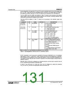
14.6.4 DC-DC BOOST (STEP-UP) CONVERTER CONTROL
DC-DC Converters 2 and 5 are boost converters which can be configured to operate in different
operating modes, using the register bits described in Table 77.
In Switch mode, the DC-DC Converter acts as a switch between VP2 and L2 or between VP5 and L5
for Converter 2 and 5 respectively. The switch is enabled (closed) by setting DCn_ENA = 1. The
switch is disabled (opened) by setting DCn_ENA = 0. Note that the switch voltage source on VP2 or
VP5 must be >1.2V to ensure reliable operation.
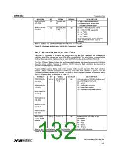
In Boost mode, the DC-DC Converters operate as step-up converters, employing current-mode
architecture, capable of powering LED lights. The output voltage can be higher than the input
voltage, but cannot be lower. Different configurations of voltage feedback are available in boost
mode, to control the output voltage in different ways. The voltage feedback mode is selected by the
DCn_FBSRC register field.
When DCn_FBSRC = 00, the converter’s output voltage is set by two external resistors connected to
FB2 or FB5. See Section 29 for Applications Information covering the selection of suitable
components.
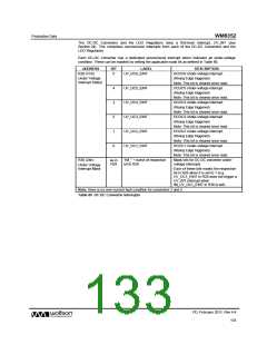
When DCn_FBSRC = 01, the converter uses the ISINKA pin as feedback and adjusts its output
voltage in order to achieve the required ISINKA current.
When DCn_FBSRC = 10, the converter uses the ISINKB pin as feedback and adjusts its output
voltage in order to achieve the required ISINKB current.
When DCn_FBSRC = 11, the converter’s output voltage is set by two internal resistors, resulting in a
fixed 5V output, suitable for USB interfaces.
The current-controlled configurations using ISINKA or ISINKB are intended for controlling a string of
serially-connected LEDs driven by one of the DC-DC boost converters. See Table 97 for a definition
of the CSn_ISEL register field which determines the required ISINKA or ISINKB current. In these
modes, external resistors connected on the FB2 or FB5 pin determine the maximum output voltage.
See Section 29 for Applications Information covering the selection of suitable components.
PD, February 2011, Rev 4.4
130
w

 WOLFSON [ WOLFSON MICROELECTRONICS PLC ]