WM8352
Production Data
14.6 CONFIGURING THE DC-DC CONVERTERS
The configuration of the DC-DC converters is described in the following sections. Some of the control
fields form part of the Custom Mode configuration settings and therefore will not require to be set in
software in some applications.
14.6.1 DC-DC CONVERTER ENABLE
The DC-DC Converters can be enabled in software using the register fields defined in Table 71. All
DC-DC converters include a soft-start feature that helps to reduce the inductor current at start up. In
order to further reduce supply in-rush current, individual converters should be programmed to start in
different time slots within the start-up sequence.
In the WM8352 ACTIVE state, the DC-DC Converters can be enabled in software using the
DCn_ENA bits. Setting these bits whilst in the Pre-Active state (see Figure 65) will not immediately
enable the corresponding DC-DC converter; these bits will only become effective once the WM8352
has reached the ACTIVE state.
Each Converter may be programmed to switch on in a selected timeslot within the start-up sequence.
The WM8352 will set the DCn_ENA field for any DC-DC converter that is enabled during the start-up
sequence. Note that setting the DCn_ENSLOT fields in software is only relevant to the Development
Mode, as these fields are assigned preset values in each of the Custom Modes.
Each Converter may be programmed to switch off in a selected timeslot within the shutdown
sequence. If a Converter is not allocated to one of the 14 shutdown timeslots, it will be disabled when
the WM8352 enters the OFF state.
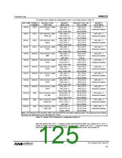
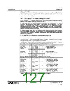
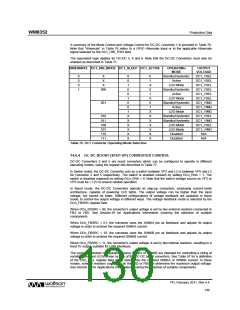
ADDRESS
BIT
LABEL
DEFAULT
DESCRIPTION
DCDCn converter enable
0 = disabled
R13 (0Dh) or
0,1,2,3 DCn_ENA
,4,5
Dependant
on CONFIG
settings
R176 (B0h)
1 = enabled
Note: internal conditions may prevent
the converter from actually switching on
- see DCDC/LDO Status register for
actual converter status.
Note: These bits can be accessed through R13 or through R176. Reading from or writing to either
register location has the same effect.
R181 (B5h) for
DC-DC1
13:10
DCn_ENSLO
T [3:0]
Dependant
on CONFIG
settings
Time slot for DC-DCn start-up
0000 = Disabled (do not start up)
0001 = Start-up in time slot 1
… (total 14 slots available)
R184 (B8h) for
DC-DC2
1110 = Start-up in time slot 14
1111 = Start up on entering ACTIVE
Time slot for DC-DCn shutdown.
0000 = Shut down on entering OFF
0001 = Shutdown in time slot 1
…. (total 14 slots available)
R187 (BBh) for
DC-DC3
9:6
DCn_SDSLO
T [3:0]
0000
R190 (BEh) for
DC-DC4
1110 = Shutdown in time slot 14
1111 = Shut down on entering OFF
R193 (C1h) for
DC-DC5
R196 (C4h) for
DC-DC6
Note: n is number between 1 and 6 that identifies the individual DC-DC converter
Table 71 Enabling and Disabling the DC-DC Converters
PD, February 2011, Rev 4.4
126
w

 WOLFSON [ WOLFSON MICROELECTRONICS PLC ]