Production Data
WM8352
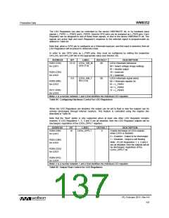
The DC-DC Converters and the LDO Regulators have
a
first-level interrupt, UV_INT (see
Section 24). This comprises second-level interrupts from each of the DC-DC Converters and the
LDO Regulators.
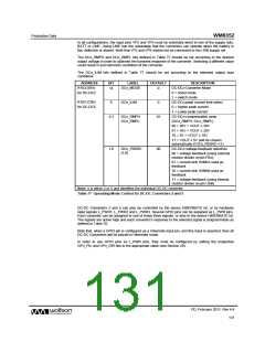
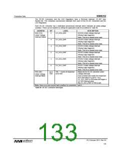
Each DC-DC Converter has a dedicated second-level interrupt which indicates an under-voltage
condition. These can be masked by setting the applicable mask bit as defined in Table 80.
ADDRESS
R28 (1Ch)
BIT
LABEL
UV_DC6_EINT
DESCRIPTION
DCDC6 Under-voltage interrupt.
(Rising Edge triggered)
5
Under Voltage
Interrupt Status
Note: This bit is cleared once read.
DCDC5 Under-voltage interrupt.
(Rising Edge triggered)
4
3
2
1
0
UV_DC5_EINT
UV_DC4_EINT
UV_DC3_EINT
UV_DC2_EINT
UV_DC1_EINT
Note: This bit is cleared once read.
DCDC4 Under-voltage interrupt.
(Rising Edge triggered)
Note: This bit is cleared once read.
DCDC3 Under-voltage interrupt.
(Rising Edge triggered)
Note: This bit is cleared once read.
DCDC2 Under-voltage interrupt.
(Rising Edge triggered)
Note: This bit is cleared once read.
DCDC1 Under-voltage interrupt.
(Rising Edge triggered)
Note: This bit is cleared once read.
R36 (24h)
as in
R28
“IM_” + name of respective
bit in R28
Mask bits for DC-DC converter under-
voltage interrupts
Under Voltage
Interrupt Mask
Each of these bits masks the respective
bit in R28 when it is set to 1 (e.g.
UV_DC1_EINT in R28 does not trigger a
UV_INT interrupt when
IM_UV_DC1_EINT in R36 is set).
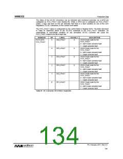
Note: there is no over-current fault condition for converters 2 and 5.
Table 80 DC-DC Converter Interrupts
PD, February 2011, Rev 4.4
133
w

 WOLFSON [ WOLFSON MICROELECTRONICS PLC ]