Production Data
WM8352
14.6.2 CLOCKING
The DC-DC converters are controlled by an internally generated clock signal from the RC Oscillator
with a constant frequency of around 2.0MHz for DC-DC 1, 3, 4 and 6, and a constant frequency of
around 1.0MHz for DC-DC 2 and 5.
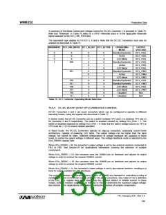
14.6.3 DC-DC BUCK (STEP-DOWN) CONVERTER CONTROL
DC-DC Converters 1, 3, 4 and 6 are buck converters which can be configured to operate in different
operating modes using the register bits described in Table 72.
In Active mode, the DC-DC Converters operate to their highest level of performance. The DC-DC
Converters will automatically select PWM or Pulse-Skipping operation according to the load
condition. This enables the power efficiency to be maximised across a wide range of load conditions.
It is possible to force the Converters to use the higher performance PWM mode; in this mode, pulse-
skipping is disabled and the output voltage is regulated by switching at a constant frequency which
improves the transient response at light loads.
In Standby/Hysteretic Mode, the DC-DC Converters disable some of the internal control circuitry in
order to reduce power consumption. The load regulation may be degraded in this mode of operation.
The efficiency data in Section 9.2.1 shows the conditions under which Standby Mode can offer better
efficiency than Active Mode.
In LDO Mode, the DC-DC Converters are reconfigured as low power LDOs.
When DCn_SLEEP = 0, the corresponding DCn_ACTIVE register bit selects between Active and
Standby/Hysteretic modes for the associated DC-DC converter.
The DCn_SLEEP register bits control the selection of LDO Mode. Setting DCn_SLEEP = 1 selects
LDO Mode. This bit takes precedence over the corresponding DCn_ACTIVE bit.
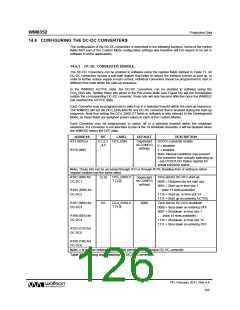
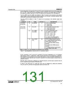
ADDRESS
BIT
0
LABEL
DEFAULT
DESCRIPTION
DC-DCn Active mode
R177 (B1h)
DC1_ACTIVE
DC3_ACTIVE
DC4_ACTIVE
DC6_ACTIVE
DC1_SLEEP
DC3_SLEEP
DC4_SLEEP
DC6_SLEEP
1
1
1
1
0
0
0
0
DC-DC Active
Options
0 = Select Standby mode
1 = Select Active mode
2
3
5
R178 (B2h)
DC-DC Sleep
Options
0
DC-DCn Sleep Mode
0 = Normal DC-DC operation
1 = Select LDO mode
2
3
5
Note: n is either 1, 3, 4 or 6 and identifies the individual DC-DC converter
R248 (F8h)
4
4
4
4
DC1_FORCE_
PWM
0
0
0
0
Force DC-DC1 PWM mode
0 = Normal DC-DC operation
1 = Force DC-DC PWM mode
Force DC-DC3 PWM mode
0 = Normal DC-DC operation
1 = Force DC-DC PWM mode
Force DC-DC4 PWM mode
0 = Normal DC-DC operation
1 = Force DC-DC PWM mode
Force DC-DC6 PWM mode
0 = Normal DC-DC operation
1 = Force DC-DC PWM mode
DCDC1 Test
Controls
R250 (FAh)
DC3_FORCE_
PWM
DCDC3 Test
Controls
R251 (FBh)
DC4_FORCE_
PWM
DCDC4 Test
Controls
R253 (FDh)
DC6_FORCE_
PWM
DCDC4 Test
Controls
Table 72 Operating Mode Control for DC-DC Converters 1, 3, 4 and 6
PD, February 2011, Rev 4.4
127
w

 WOLFSON [ WOLFSON MICROELECTRONICS PLC ]