WM8352
Production Data
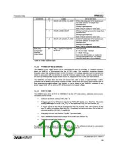
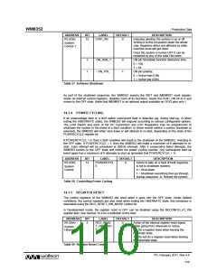
DESCRIPTION
ADDRESS
BIT
LABEL
DEFAULT
R3 (03h)
15
CHIP_ON
0
Indicates whether the system is on or off.
Writing 0 to this bit powers down the whole
chip. Registers which are affected by state
machine reset will get reset.
System
Control 1
Once the system is turned OFF it can be
restarted by any of the valid ON event.
3
1
ON_DEB_T
ON_POL
0
1
ON pin Shutdown function debounce time
0 = 10s
1 = 5s
ON pin polarity:
0 = Active high (ON)
1 = Active low (/ON)
Table 57 Software Shutdown
As part of the shutdown sequence, the WM8352 asserts the /RST and /MEMRST reset signals,
resets its internal control registers, disables most of its functions, resets the CHIP_ON bit to 0 and
moves to the OFF state. (Note that /MEMRST is an optional output available on GPIO pins only.)
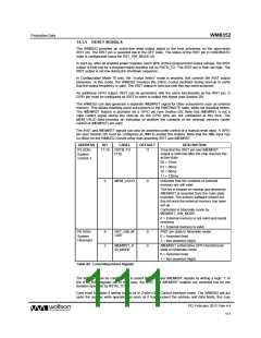
14.3.4 POWER CYCLING
If an undervoltage fault or a limit switch overcurrent fault is detected (eg. during start-up, or when
exiting the HIBERNATE state), the WM8352 will respond according to various configurable options.
The Limit Switch and each of the DC Converters and LDO Regulators may be programmed to
shutdown the system in the event of a fault condition. In these events (where a system shutdown is
selected), the WM8352 will either shut down or will attempt to re-start, depending on the state of the
POWERCYCLE register bit.
If POWERCYCLE = 0, then a fault condition will result in the shutdown of the WM8352, reverting to
the OFF state. If POWERCYCLE = 1, then the WM8352 will make a maximum of 8 attempts to re-
start. Each attempt will be scheduled at 200ms intervals. After 8 consecutive failed attempts, the
WM8352 reverts to the OFF state and resets the power cycling counter. Any subsequent start-up
event again has a maximum of 8 attempts to start up (provided that POWERCYCLE = 1).
ADDRESS
BIT
LABEL
DEFAULT
DESCRIPTION
R3 (03h)
13
POWERCYCL
E
0
Action to take on a fault (if fault response
is set to shutdown system):
System
Control
0 = Shut down
1 = Shutdown everything then go through
startup sequence. ie. Reboot the system.
Table 58 Controlling Power Cycling
14.3.5 REGISTER RESET
The control registers of the WM8352 are reset when it goes into the OFF state. Under default
conditions, the control registers are also reset when exiting the HIBERNATE state; this behaviour is
selectable using the REG_RESET_HIB_MODE control bit.
In Development mode, the register reset in OFF can be disabled using the RECONFIG_AT_ON
register field. See Section 14.4 for a definition of this field.
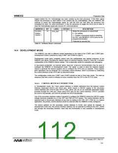
ADDRESS
BIT
LABEL
DEFAULT
DESCRIPTION
R5 (05h)
5
REG_RESE
T_HIB_MOD
E
0
Action of the internal register reset signal
when going from Hibernate to Active.
System
Hibernate
0 = Do a register reset when leaving the
hibernate state.
1 = Do not do a register reset when leaving
the hibernate state
Table 59 Register Reset Control
PD, February 2011, Rev 4.4
110
w

 WOLFSON [ WOLFSON MICROELECTRONICS PLC ]