WM8352
Production Data
By default, the DO_CONF output will be set low when the WM8352 enters the OFF state and set
high on every transition from OFF to ACTIVE, re-triggering the external ‘genie’. Also, by default, the
internal control registers will be reset when the WM8352 enters the OFF state. This behaviour can be
changed using the RECONFIG_AT_ON register bit. If RECONFIG_AT_ON is set to 0, then the
control registers will not be reset when going into the OFF state, and the DO_CONF output will
remain set high after the first powering up of the chip, regardless of subsequent state transitions.
De-selection of RECONFIG_AT_ON should be used with caution, as this can potentially lead to
system failures in some applications. If RECONFIG_AT_ON is set to 0, and an OFF event occurs,
then it is possible that control registers will not be set to the intended start-up values when the
WM8352 subsequently returns to the ON state. The impact of this will depend upon the hardware
and software of the particular target application, and is not necessarily a risk in every instance.
Please contact Wolfson Applications support if further guidance is required on this topic.
Note that RECONFIG_AT_ON should never be set to 0 in Custom Modes 01, 10 or 11. Setting this
bit to 0 may result in erroneous behaviour and deviation from the custom configuration settings.
Under default settings, the control registers are always reset in the OFF state.
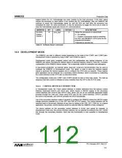
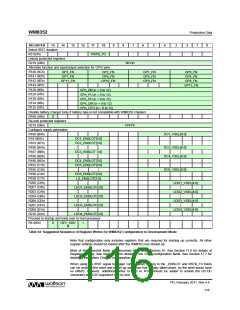
The register fields DO_CONF and RECONFIG_AT_ON are defined in Table 63.
ADDRESS
BIT
LABEL
DEFAULT
DESCRIPTION
R6 (06h)
12
CONFIG_D
ONE
0
Tells the system that the PIC micro has
completed its programming.
Interface
Control
0 = Programming still to be done
1 = Programming complete
Only applies when CONFIG pins[1:0] = 00.
11
RECONFIG
_AT_ON
1
Selects whether to reset the registers in the
OFF state and whether to reload the device
configuration from the PIC when an ON
event occurs.
0 = Do not reset registers in the OFF state.
Do not load configuration data when an ON
event occurs.
1 = Reset registers in the OFF state. Load
configuration from the PIC when an ON
event occurs.
Note that, in development mode, the device
configuration from the PIC is always loaded
when first powering up the chip.
This bit must always be set to default (1) in
Custom Modes 01, 10 and 11.
Table 63 Start-Up Control in Development Mode
Note: if the WM8352 enters the BACKUP state as a result of an undervoltage condition (see
Section 18), then the control registers will be reset, but DO_CONF will remain high. When the supply
voltage rises and device comes out of BACKUP, the DO_CONF output will still be high. If the
DO_CONF signal is used to trigger an external ‘genie’ device, then this may not work, as the
DO_CONF has remained high through the BACKUP state transition, and the WM8352 device will
become locked in the PRE-ACTIVE state when an ON event occurs.
This problem may be avoided by ensuring that the ‘genie’ monitors the LINE voltage in order to
recognise the undervoltage condition, and that it verifies the I2C Acknowledge signal on the
secondary interface (GPIO10 and GPIO11) to determine whether it can execute its programming
function.
PD, February 2011, Rev 4.4
114
w

 WOLFSON [ WOLFSON MICROELECTRONICS PLC ]