WM8352
Production Data
14 POWER MANAGEMENT SUBSYSTEM
14.1 GENERAL DESCRIPTION
The WM8352 provides 6 DC-DC Converters and 4 LDO Regulators which each deliver high
efficiency across a wide range of line and load conditions. These power management components
are designed to support application processors and associated peripherals. They are also suitable for
providing power to the analogue and digital functions of the on-board CODEC and GPIO features.
The output voltage of each of the converters and regulators is programmable in software through
control registers.
The WM8352 has a number of operating states which are either selected by software control or are
selected autonomously according to the available power supply conditions. A low power active
‘Hibernate’ state is provided, with programmable characteristics. The ‘Backup’ and ‘Zero’ states are
selected autonomously when the available supply voltages do not permit full operation of the
WM8352.
Four configuration modes are provided, selected by hardware control. Development Mode gives
complete control over the configuration and start-up behaviour of the WM8352. Three different
Custom Modes each have a defined set of configuration parameters, which determine the start-up
timing and output voltage of each of the DC-DC Converters and LDO Regulators. The configuration
of each of the GPIO pins is also contained with the configuration modes definitions.
14.2 POWER MANAGEMENT OPERATING STATES
The WM8352 autonomously controls the power-up and power-down sequencing for itself and for
other connected devices. It also selects the most appropriate power source available at any given
time (see Section 17). The stable states of the WM8352 are:
ACTIVE - All WM8352 functions can be used. The WM8352 enters the ACTIVE state after a valid
start-up event (see Section 14.3.1), provided that no fault condition occurred during start-up.
HIBERNATE - This is an alternative active state with programmable characteristics, allowing an
optional low power system condition. The internally generated supply voltages can be individually
enabled or disabled as desired. The WM8352 enters the HIBERNATE state from ACTIVE by setting
the HIBERNATE register bit or when commanded via a GPIO pin configured as a HIBERNATE
alternate function.
OFF - All DC-DC converters and regulators LDO2, LDO3 and LDO4 are disabled. LDO1 may remain
active (See Section 14.7.4). The VRTC regulator remains active and powers the always-on functions
(such as crystal oscillator and RTC.) Register settings are restored to default settings. Trickle
charging for the main battery is enabled by default. The WM8352 enters the OFF state from ACTIVE
if a shutdown event occurs (see Section 14.3.3), or if the power source falls below the shutdown
threshold (see Section 18). The WM8352 enters the OFF state from BACKUP if a power source
greater than the UVLO threshold becomes available.
BACKUP - The crystal oscillator and RTC are enabled, powered from the backup power (VRTC)
supply. All other functions are disabled. The WM8352 enters the BACKUP state from OFF if the
power source falls below the UVLO threshold (see Section 18), and provided that backup power
(VRTC) is available (i.e. LINE falls below the UVLO level but VRTC remains above the Power-On
Reset threshold).
ZERO - All functions are disabled and all data in registers is lost. The WM8352 goes into this state
when no power source is available and VRTC falls below the Power-On Reset threshold.
The Active state can only be entered via the PRE-ACTIVE state. In Development Mode, the Pre-
Active state is the state in which the WM8352 start-up parameters may be defined, prior to the start-
up sequence being triggered. The ACTIVE state is only entered on completion of the start-up
sequence.
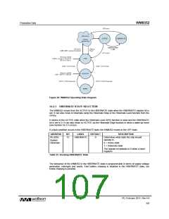
The WM8352 operating states and valid transitions are illustrated in Figure 64.
PD, February 2011, Rev 4.4
106
w

 WOLFSON [ WOLFSON MICROELECTRONICS PLC ]