WM8352
Production Data
14.3 POWER SEQUENCING AND CONTROL
14.3.1 STARTUP
The WM8352 moves from OFF or HIBERNATE states to the ACTIVE state when a startup event
occurs. Startup events include:
.
A trigger signal on the ON pin lasting more than 40ms. The active polarity of this input is
set by the register field ON_POL.
.
A trigger signal on a GPIO pin configured as /WAKEUP lasting more than 40ms. The
active polarity of this input is set by GPn_CFG for the applicable GPIO pin (see
Section 20).
.
A trigger signal on a GPIO pin configured as PWR_ON input lasting more than 40ms. The
active polarity of this input is set by GPn_CFG for the applicable GPIO pin (see
Section 20).
.
.
.
Programmed ALARM from RTC module, if enabled (see Section 22).
Wall adaptor plug-in (WALL_FB rises above 4.0V).
USB plug-in (USB pin rises above 4.0V).
The start-up events are only valid provided also that the available supply voltage, sensed on the
LINE pin, is greater than the start-up threshold set by PCCMP_ON_THR, as defined in Section 18.
Start-Up by Wall adaptor plug-in occurs when the Wall Adapter feedback pin detects a voltage
greater than 4.0V. See Section 17.1 for a description of the WALL_FB pin function.
Start-Up by USB plug-in occurs when the USB voltage rises above the LINE voltage. If USB
Suspend mode is invoked, then USB plug-in starts the WM8352 on battery power, if available. When
USB Suspend Mode is not invoked, this start-up event will lead to starting the WM8352 on USB
power, and USB 100mA trickle charging of the battery is enabled.
Note that applying a battery voltage is not a start-up event, i.e. connecting a battery pack does not
start the WM8352. The WM8352 starts up on battery power if a startup event occurs and battery
power is the only power source available, provided the battery voltage is above the startup threshold.
(The start-up threshold is set by PCCMP_ON_THR, as defined in Section 18.)
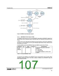
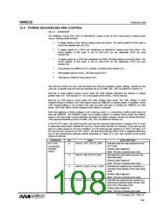
In the ACTIVE state, the host processor can read the Interrupt status fields in Register R31 in order
to determine what action initiated the start-up. These fields indicate, for example, if the start-up was
due to a reset caused by an error condition, or if the start-up was caused by a PWR_ON input, or if
the start-up was caused by an RTC alarm. The first-level interrupt WKUP_INT is triggered whenever
any of the second-level interrupt events described in Table 56 is set. See Section 24 for further
details of Interrupt.
ADDRESS
BIT
LABEL
DESCRIPTION
R31 (1Fh)
6
WKUP_OFF_STATE_EINT
Indicates that the chip started from the
OFF state.
Comparator
Interrupt
Status
(Rising Edge triggered)
Note: This bit is cleared once read.
5
4
WKUP_HIB_STATE_EINT
WKUP_CONV_FAULT_EINT
Indicated the chip started up from the
hibernate state.
(Rising Edge triggered)
Note: This bit is cleared once read.
Indicates the wakeup was caused by a
converter fault leading to the chip being
reset.
(Rising Edge triggered)
Note: This bit is cleared once read.
3
WKUP_WDOG_RST_EINT
Indicates the wakeup was caused by a
watchdog heartbeat being missed, and
hence the chip being reset.
(Rising Edge triggered)
Note: This bit is cleared once read.
PD, February 2011, Rev 4.4
108
w

 WOLFSON [ WOLFSON MICROELECTRONICS PLC ]