Production Data
WM8352
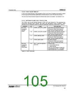
13.12.6 ZERO CROSS TIMEOUT
A zero-cross timeout function is also provided so that if zero cross is enabled on the input or output
PGAs the gain will automatically update after a timeout period if a zero cross has not occurred.
The zero-cross timeout function requires the internal slow clock to be enabled - see Section 12.3.6.
13.12.7 INTERRUPTS AND FAULT PROTECTION
The CODEC has its own first-level interrupt, CODEC_INT (see Section 24). This comprises four
second-level interrupts which indicate Jack detect and Microphone current conditions. These
interrupts can be individually masked by setting the applicable mask bit(s) as described in Table 54.
ADDRESS
BIT
LABEL
DESCRIPTION
Left channel Jack detection interrupt.
(Rising and Falling Edge triggered)
Note: This bit is cleared once read.
Right channel Jack detection interrupt.
(Rising and Falling Edge triggered)
Note: This bit is cleared once read.
Mic short-circuit detect interrupt.
(Rising and Falling Edge triggered)
Note: This bit is cleared once read.
Mic detect interrupt.
R31 (1Fh)
11
CODEC_JCK_DET_L_EINT
Comparator
Interrupt
Status
10
9
CODEC_JCK_DET_R_EINT
CODEC_MICSCD_EINT
CODEC_MICD_EINT
8
(Rising and Falling Edge triggered)
Note: This bit is cleared once read.
Interrupt mask.
R39 (27h)
11:8
“IM_” + name of respective
bit in R31
Comparator
Interrupt
Status Mask
0 = Do not mask interrupt.
1 = Mask interrupt.
Each bit in R39 enables or masks the
corresponding bit in R31. The default
value for these bits is 0 (unmasked).
Table 54 CODEC Interrupts
PD, February 2011, Rev 4.4
105
w

 WOLFSON [ WOLFSON MICROELECTRONICS PLC ]