W90N745CD/W90N745CDG
START or Repeated START signal
When the bus is free/idle, meaning no master device is engaging the bus (both SCL and SDA lines
are high), a master can initiate a transfer by sending a START signal. A START signal, usually
referred to as the S-bit, is defined as a HIGH to LOW transition on the SDA line while SCL is HIGH.
The START signal denotes the beginning of a new data transfer.
A Repeated START (Sr) is a START signal without first generating a STOP signal. The master uses
this method to communicate with another slave or the same slave in a different transfer direction (e.g.
from writing to a device to reading from a device) without releasing the bus.
The I2C core generates a START signal when the START bit in the Command Register (CMDR) is set
and the READ or WRITE bits are also set. Depending on the current status of the SCL line, a START
or Repeated START is generated.
STOP signal
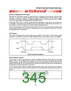
The master can terminate the communication by generating a STOP signal. A STOP signal, usually
referred to as the P-bit, is defined as a LOW to HIGH transition on the SDA line while SCL is HIGH.
SCL
SDA
START condition
STOP condition
START and STOP conditions
Slave Address Transfer
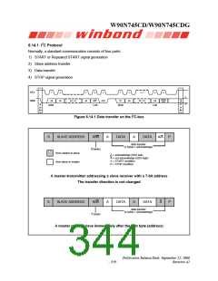
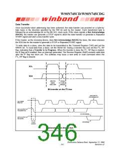
The first byte of data transferred by the master immediately after the START signal is the slave
address. This is a 7-bits calling address followed by a RW bit. The RW bit signals the slave the data
transfer direction. No two slaves in the system can have the same address. Only the slave with an
address that matches the one transmitted by the master will respond by returning an acknowledge bit
by pulling the SDA low at the 9th SCL clock cycle.
The core treats a Slave Address Transfer as any other write action. Store the slave device’s address
in the Transmit Register (TxR) and set the WRITE bit. The core will then transfer the slave address on
the bus.
MSB
LSB
A6
A5
A4
A3
A2
A1
A0
R/W
slave address
The first byte after the START procedure
- 340 -

 WINBOND [ WINBOND ]