TMC8462 Datasheet • Document Revision V1.4 • 2018-May -09
187 / 204
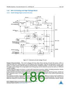
Upon exceeding the activation threshold, a time proportional to the excess current is required to switch off
the output. This way, short time peak currents can safely be switched, e.g. when long cables or capacitive
loads are attached.
An interrupt flag informs about an active overcurrent condition. The short condition will be cleared once
the output polarity is toggled.
Input Characteristics The inputs automatically adapt to the supply voltage range. In low voltage range
(up to 5V operation), a fast digital Schmitt trigger is used for evaluation of the input logic levels. It provides
a TTL compatible input level.
In the high voltage range, the input path switches to a threshold voltage just at half supply voltage range.
Both modes add a hysteresis in order to avoid oscillation with slow transitions on the inputs. When
switching to slow slope operation, the input lines become filtered in order to eliminate reaction to short
voltage spikes. In this mode, the half level comparator is always used. A minimum pull down current of
10µA is always drawn in order to ensure a defined level on an open input.
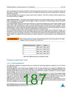
The inputs allow a differential mode between each two combined inputs (see combination table). It is
important to set both inputs to the same slope setting in this case. Both input lines deliver a comparison
result using each one voltage comparator. This allows direct attachment of differential voltage sources
like encoders. The addition of input protection resistor networks is recommended in case long cables are
used.
When driving inductive loads a freewheeling diode must be provided to the high
voltage I/O pins to prevent from latch-up.
WARNING
Differential input pair Input 1
Input 2
A
B
C
D
MFC_HV0 MFC_HV3
MFC_HV1 MFC_HV4
MFC_HV2 MFC_HV5
MFC_HV6 MFC_HV7
Table 209: Differential input combination table
The inputs are read via Input 1 result.
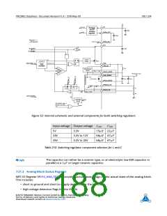
7.21.2 Switching Regulators
The TMC8462 integrates a programmable and a fixed buck switching regulator designed for up to 500mA
of output current.
The fixed regulator has a fixed output voltage of 3.3V. Its main purpose is to supply the TMC8462 I/Os
and the digital part via the 1.8V linear regulators. This regulator comes with an integrated 800mA 5.5V
Schottky diode which minimizes part count, when an external 5V supply is available. In case of a higher
supply voltage, use an external Schottky diode instead.
The second regulator can be programmed to any output voltage ranging from 1.2V up to the supply voltage
level. It can be used to generate an additional 3.3V supply or any additional voltage like 5V, 12V or 24V
required for operation of peripheral circuits or the high voltage I/O lines. An integrated common linear 5V
regulator starts up the switch regulators. Cascading of both switch regulators also is possible.
Both regulators support a wide range of L and C components. This is enabled by a programmable current
feedback loop gain and compensation capacity. Both switching regulators provide optional dampening of
the coil oscillations to reduce electromagnetic emission.
©2018 TRINAMIC Motion Control GmbH & Co. KG, Hamburg, Germany
Terms of delivery and rights to technical change reserved.
Download newest version at www.trinamic.com

 TRINAMIC [ TRINAMIC MOTION CONTROL GMBH & CO. KG. ]