TMC8462 Datasheet • Document Revision V1.4 • 2018-May -09
186 / 204
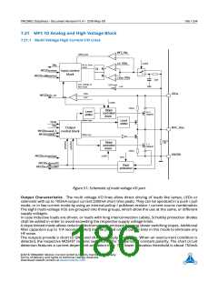
7.21 MFC IO Analog and High Voltage Block
7.21.1 Multi Voltage High Current I/O Lines
MFC_HVy
1/2 VIOx
differential
SLOPE
HV or slow
slope
INx
Q
S
R
MFCIOx.slope
Input control
block
MFCIOx.differential
17/40 VIOx
1µs
low voltage &
fast slope
0.3V hyst.
1.2V
VIOx
5.5V
VIOx
MFCIOx.hv_on
SLOPE
100µA
Slope
controlled
driver
Level
shifter
10
MOSFET
Weak high
Level
shifter
OUTx
OEx
Output
MFC_HVx
MFCIOx.weak_h
MFCIOx.weak_l
control block
Weak low
10µA ||
1.5M
Slope
controlled
driver
5
MOSFET
100µA
GNDIO
SLOPE
MFCIOx.slowslope
OUTx
MFCIOx.short2VS
Short
protection
MFCIOx.short2GND
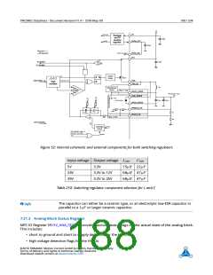
Figure 51: Schematic of multi voltage I/O port
Output Characteristics The multi voltage I/O lines allow direct driving of loads like lamps, LEDs or
solenoids with up to 100mA output current (200mA short time peak). They can be operated in a push / pull
mode, or in low current mode by using an internal pullup / pulldown resistor / current source combination.
The eight multi-voltage I/Os are grouped into three groups, which allow the use at the same, or different
supply voltages.
In case inductive loads are driven, or loads with long interconnection cables, Schottky protection diodes
shall be added in order to avoid exceeding the respective supply voltage limits.
A slope limited mode allows reducing electromagnetic emission by using slower switching slopes. Additional
filter capacitors (up to 1nF recommended) may be placed on the output lines in this mode to eliminate any
HF noise.
The outputs provide a short to GND and short to supply protection. When an overcurrent condition is
detected, the respective MOSFET remains switched off for the period of constant polarity. The short circuit
detection features a current dependent activation time. The lower activation threshold is about 150mA.
©2018 TRINAMIC Motion Control GmbH & Co. KG, Hamburg, Germany
Terms of delivery and rights to technical change reserved.
Download newest version at www.trinamic.com

 TRINAMIC [ TRINAMIC MOTION CONTROL GMBH & CO. KG. ]