TMC8462 Datasheet • Document Revision V1.4 • 2018-May -09
172 / 204
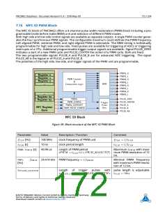
7.15 MFC IO PWM Block
The MFC IO block of TMC8462 offers a 4-channel pulse width modulation (PWM) block including a pro-
grammable brake before make (BBM) unit and selection of different PWM modes.
Both high side and low side control signals are available as separate outputs. A single PWM counter gener-
ates the four synchronous PWM signals. The configurable maximum count defines the PWM frequency.
Left aligned PWM, centered PWM, and right aligned PWM is selectable. The BBM timing is individually
programmable for high side and low side. Fixed pulses are available for triggering of ADCs or triggering
interrupts of a CPU. Additional programmable trigger output signals are available. Signal PULSE_ZERO
indicates a start of a new PWM cycle and PULSE_CENTER the center of a PWM cycle. Both are fixed.
The two programmable signals PULSE_A and PULSE_B are for advanced ADC triggering. The signal
PULSE_AB is the logical or of PULSE_A and PULSE_B.
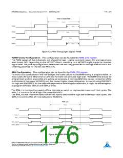
The polarities of the high side, low side, and trigger signals of the PWM unit are programmable.
Figure 39: Block structure of the MFC IO PWM Block
Parameter
fCLK [Hz]
tCLK [s]
Value
Description / Function
clock frequency of PWM unit
clock period length
Comment
100 MHz
10 ns
fCLK = 1/tCLK
tCLK = 1/fCLK
max. tP W M [s]
40.96 us
Length of PWM period
Maximum tP W M with maxi-
mum PWM resolution of 12
bit.
tPWM
=
tCLK
∗
(1+PWM_MAXCNT
)
min.
[Hz]
fP W M 24.414 kHz PWM frequency = 1/tP W M
Minimal PWM frequency
with maximum PWM resolu-
tion of 12 bit.
tP ULSE_LENGT H
Length of trigger pulses with pulse length is adjustable
tP ULSE_LENGT H
PULSE_LENGTH ∗ tCLK = 10ns
tCLK
=
©2018 TRINAMIC Motion Control GmbH & Co. KG, Hamburg, Germany
Terms of delivery and rights to technical change reserved.
Download newest version at www.trinamic.com

 TRINAMIC [ TRINAMIC MOTION CONTROL GMBH & CO. KG. ]