TMC8462 Datasheet • Document Revision V1.4 • 2018-May -09
171 / 204
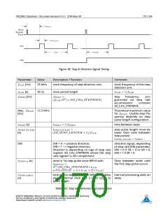
Step Rate Accumulation Constant The step direction accumulation constant determines the time
tST EP between two successive step pulses – this is actually the step rate. Each internal PWM clock
accumulates an accumulator according to
a
=
a
+
c
with the accumulator constant
c
. Toggle of the MSB
of the accumulator register a triggers a step pulse. With this principle, the step frequency is smarter
adjustable compared to a simple frequency divider. Writing = 0 clears the accumulator and stops the
c
step pulse generation. The step pulse frequency calculates as fST EP = (fCLK/232) ∗ c.
Step Counter The step counter counts the number of steps, taking the direction into account. This is
a read only register. For initialization to zero a configuration bit within the step direction configuration
register hast to be written.
Step Target The step target defines the number of steps to be made for the step mode until stop.
This register can be overwritten at any time. When the number of steps has been made, the unit stops
outputting S/D pulses. When read, it gives the remaining numbers that must still be made.
Step Compare This register holds a compare value in numbers of step pulses. In target mode, the
number of steps to be made is configured in this register. Depending on the motor’s pole count and the
microstep resolution, the numbers of steps represent a certain distance.
Next Step Rate The next step rate register contains a value of the same format as the step rate register.
This value is automatically written into the step rate register after a successful compare of the step compare
value and the actual step counter. This way, simple motion profiles can be realized.
Step Length The duration of the step pulse – the step length – signal is programmable for adaption to
external power stages.
Note
Maximum step length: The step pulse length tST EP _P ULSE must be lower than
the time tST EP between step pulses to actually see step pulses at the outputs.
The condition tST EP _P ULSE < tST EP must be ensured by the application.
Step-to-Direction Delay The delay between the first step pulse after a change of the direction is pro-
grammable for adaption to external power stages to take external delay paths into account.
Step Direction Unit Configuration The step direction configuration defines the mode of operation
(continuous or finite number of step pulses), polarity of step pulse signal and direction signal. One bit is
for zeroing of step pulse counter. On bit is for enabling and disabling of the step pulse unit and compare
mode.
Interrupt Output Signal An IRQ signal TARGET_REACHED of a single clock pulse length indicates that a
certain target position has been reached reached in terms of step counts.
©2018 TRINAMIC Motion Control GmbH & Co. KG, Hamburg, Germany
Terms of delivery and rights to technical change reserved.
Download newest version at www.trinamic.com

 TRINAMIC [ TRINAMIC MOTION CONTROL GMBH & CO. KG. ]