TMC248-LA DATASHEET (Rev. 1.01 / 2013-MAR-26)
21
frequency of roughly 20 kHz, a base clock frequency of 20 MHz (=210 x 20 kHz) is required to yield a 10
bit PWM. A 16 MHz clock frequency will allow realizing a 9 bit PWM with 31 kHz, or a resolution of 800
PWM steps with 20 kHz. This is a feasible value for most standard 8 bit or better microcontrollers.
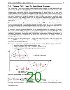
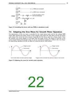
Basically, one motor coil is driven with a PWM, which duty cycle is modulated using a sine wave. The
other coil with a cosine modulated PWM. Assuming, that the system supply voltage would exactly
match the motor voltage required for nominal current, the PWM duty cycle will be altered between
100% for maximum positive current and 0% for maximum negative current. As this is not a typical
constellation, the PWM modulation required to match the motor needs to be calculated.
The PWM modulation is calculated as:
ꢡꢂꢀꢛꢜ
ꢂꢀꢛꢜꢝꢞꢟꢠ ꢢꢣꢤ ꢥ ꢣꢦꢧꢤꢨ
ꢓꢔꢕꢖꢗꢘꢙ ꢃ ꢚ
ꢩ
PWMAmpl PWM amplitude required to reach the nominal motor current. Half of this amplitude is
applied in positive direction (additional to 50% duty cycle), and half of it is applied in
negative direction (subtracted from 50% duty cycle)
ICOILpeak
RCOIL
VM
Nominal peak coil current of the motor, i.e. ICOILRMS * 1.41
Resistance of the motor coil
Motor driver supply voltage (may be measured in the application)
Velocity dependent back EMF voltage of the motor. It is measured in V/rad/s.
At standstill VBEMF is zero and can be ignored for low RPM.
For higher velocities, multiply it by the angular velocity of the motor.
VBEMF
EXAMPLE
A 1A RMS motor with 6.5Ohm coil resistance is to be operated from a 12V supply at low velocity.
ꢮꢬꢯꢰ
ꢪꢖ ꢫ ꢪꢬꢭꢪ
ꢃ ꢲꢬꢳꢮ
ꢢꢪꢱꢣ ꢥ ꢲꢣꢩ
Therefore, the duty cycle needs to be modulated between 0.5 + 0.76/2 = 88% for the positive sine wave
peak and 0.5 - 0.76/2 = 12% for the negative sine wave peak.
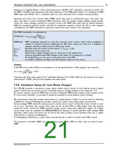
7.3.2 Hardware Setup for Low Noise Chopper
The TMC248 provides a standalone mode, which allows direct control of coil polarity using a digital
signal. Further, the coil current can be controlled using an analog voltage in the range 0 V… 3 V.
As current control is done by PWM duty cycle, the integrated PWM based analog current control of the
IC is not used. Therefore, in principle it would be possible to work without sense resistors.
We recommend using the analog current limit as a safety feature. Further it can be used for allowing
a fallback to classical fullstepping at higher velocity (in order to also allow faster movements):
During voltage PWM mode the analog current control can be used to limit the motor current in case
of an error. Therefore, the current limit must be set at least 20% to 30% higher than the desired
maximum motor current for PWM operation (peak current value plus additional ripple). The mixed
decay mode must be switched off (MDAN=MDBN=VCC), because it would interfere with voltage PWM
operation. Both motor coil limits can be set to the same analog current limiting value: for a safety
limit and for a change to fullstepping.
In fullstepping switching to a lower value may be desired in order to match motor RMS current.
The processor controlled PWM uses the polarity inputs (PHA, PHB) for both coils to control motor
PWM.
www.trinamic.com

 TRINAMIC [ TRINAMIC MOTION CONTROL GMBH & CO. KG. ]