TMC248-LA DATASHEET (Rev. 1.01 / 2013-MAR-26)
22
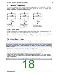
PHA
µC-PWM (sine modulated)
PHB
INA
INB
µC-PWM (cosine modulated)
µC port pin (switch current
limit for fullstepping)
TMC248
R3
R1
+VCC
SPE
Figure 7.4 Controlling the driver with two PWMs in standalone mode
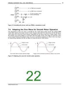
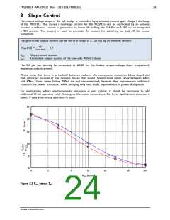
7.4 Adapting the Sine Wave for Smooth Motor Operation
The optimization of the sine wave is possible for the mixed decay mode and for the voltage PWM
mode. After reaching the target current in each chopper cycle, both, the slow decay and the fast decay
cycle reduce the current by some amount. Especially the fast decay cycle has a larger impact. Thus,
the medium coil current always is a bit lower than the target current. This leads to a flat line in the
current shape flowing through the motor. It can be corrected, by applying an offset to the sine shape.
In mixed decay operation via SPI, an offset of 1 does the job for most motors.
Target current
Coil current
Target current
Coil current
I
I
t
t
Coil current does not have optimum shape
Target current corrected for optimum shape of coil current
Figure 7.5 Adapting sine wave for smooth motor operation
www.trinamic.com

 TRINAMIC [ TRINAMIC MOTION CONTROL GMBH & CO. KG. ]