TMC248-LA DATASHEET (Rev. 1.01 / 2013-MAR-26)
20
7.3 Voltage PWM Mode for Low Noise Chopper
The TMC248 uses a cycle-by-cycle based chopper system, because it brings the best performance over
a wide range of velocities. It regulates the current by terminating each chopper cycle as soon as the
target current has been reached. This direct current regulation provides good dampening of motor
resonance, low motor power loss and automatic adaptation to the specific motor. On the other hand,
chopper stability requires good decoupling between both motor coils and it needs a precise layout of
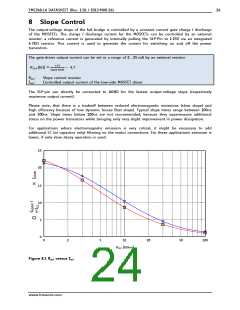
the high current paths. Instabilities caused by magnetic coupling in the motor or by coupling of the
coil current regulators due to electric coupling can lead to chopper noise and fine vibrations. Under
normal conditions, these will not do any harm. In applications, where the motor moves very slowly
or where precise standstill with low mass on the motor axis is required, a voltage PWM chopper is a
good choice.
The low noise feed forward chopper principle uses a voltage PWM controlled driving rather than
current controlled driving. This is possible, because the stepper motor has a certain coil resistance.
This resistance converts an externally applied voltage to current. As long as the motor velocity is low,
back EMF caused by the motor rotation does not need to be taken into account.
At increasing velocities, the motors back EMF has an increasing influence and influences coil current.
This can be compensated by increasing the driver voltage with increasing velocity. Effects like motor
temperature dependency of the coil resistance should be taken into account, in case the motor
operates in an increased temperature range. The described compensation principle can be realized in
a completely feed-forward way, based on the motor data, or by measuring the effective current and
adding a regulation loop.
The chopper principle described generates a certain motor voltage by toggling each motor phase with
a certain PWM frequency. Therefore the motor full bridges either switch on the motor current in one
direction or in the opposite direction.
This way, the duty cycle of toggling the coil polarity produces a certain effective voltage on the coils:
-
-
-
A 50 percent duty cycle gives a mean current of zero.
A higher or lower duty cycle gives a positive or negative current.
A high PWM resolution will bring a high microstep resolution.
I
+VM
effective coil current
-VM
coil voltage PWM
t
+VM
-VM
+VM
-VM
coil voltage PWM
coil voltage PWM
50% dutycylce
Figure 7.3 Voltage PWM generates motor current
7.3.1 Calculating the PWM for Low Noise Chopper
A microcontroller or an FPGA can be used for generating the two PWMs required to drive the motor.
For a 256 microstep resolution a PWM resolution of 9 to 10 bit is required. Assuming a target chopper
www.trinamic.com

 TRINAMIC [ TRINAMIC MOTION CONTROL GMBH & CO. KG. ]