TMC248-LA DATASHEET (Rev. 1.01 / 2013-MAR-26)
17
6.2.1 Making the Circuit Short Circuit Proof
In most applications, a short circuit does not describe only one special condition. It typically involves
inductive, resistive and capacitive components. Worst events are unclamped switching events, because
huge voltages can build up in inductive components and result in a high energy spark going into the
driver, which can destroy the power transistors.
Note:
Never disconnect the motor during operation as this can destroy the power transistors!
An absolute protection against random short circuit conditions is not given, but pre-cautions can be
taken to improve robustness of the circuit:
In a short condition, the current can become very high before it is interrupted by the short detection,
due to the blanking during switching and internal delays. The high-side transistors allow a high
current flowing for the selected blank time. The lower the external inductivity, the faster the current
climbs. If inductive components are involved in the short, the same current will shoot through the
low-side resistor and cause a high negative voltage spike at the sense resistor. Both, the high current
and the voltage spikes are dangerous for the driver.
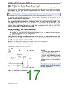
PROCEED AS FOLLOWS, IF SHORT CIRCUITS ARE EXPECTED:
1. Protect SRA/SRB inputs using a series resistance.
2. Increase RSH (high side overcurrent detection resistor) to limit the maximum transistor current.
Use the same value as for the sense resistors.
3. Set the blank time as short as possible.
The second point effectively limits the short circuit current, because the upper driver transistor with
fixed ON gate voltage of 6V forms a constant current source together with its internal resistance and
the high side overcurrent detection resistor RSH.
A positive side effect is that only one type of low resistive resistor is required.
The drawback is that power dissipation increases.
VS
100nF
RDIV
VT
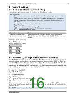
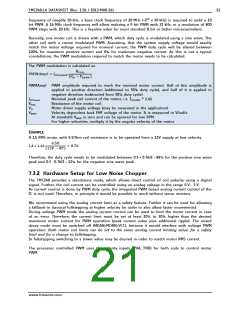
Example:
+VM
100R
RSH
GND
A 0.33 Ohms sense resistor allows for
roughly 1 A motor coil current.
A high side short detection resistor of
0.33 Ohms limits maximum high side
transistor current to typically 4A
during a short circuit condition. The
schematic shows the modifications to
be done.
RSH=RSA=RSB
internal
reference
27R
INA/INB
up to3V
18R
RDIV values for
Microstep:
Fullstep:
CVM
18R
12R
SRA
100R
100R
The effectiveness of the steps
described above should be tested in
the given application!
SRB
RSA
RSB
GND
Figure 6.1 Schematic with RSH=RSA=RSB
www.trinamic.com

 TRINAMIC [ TRINAMIC MOTION CONTROL GMBH & CO. KG. ]