TMC248-LA DATASHEET (Rev. 1.01 / 2013-MAR-26)
24
8 Slope Control
The output-voltage slope of the full bridge is controlled by a constant current gate charge / discharge
of the MOSFETs. The charge / discharge current for the MOSFETs can be controlled by an external
resistor: a reference current is generated by internally pulling the SLP-Pin to 1.25V via an integrated
4.7K resistor. This current is used to generate the current for switching on and off the power
transistors.
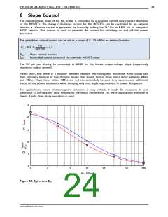
The gate-driver output current can be set in a range of 2… 25 mA by an external resistor:
ꢄꢷꢸ
ꢡꢁꢜꢴꢏꢵꢰꢒ ꢶ ꢹ ꢉꢏꢼꢽꢒ ꢥ ꢉꢭꢬꢳ
ꢌꢺꢻ
RSLP:
IOUT:
Slope control resistor
Controlled output current of the low-side MOSFET driver
The SLP-pin can directly be connected to AGND for the fastest output-voltage slope (respectively
maximum output current).
Please note, that there is a tradeoff between reduced electromagnetic emissions (slow slope) and
high efficiency because of low dynamic losses (fast slope). Typical slope times range between 100ns
and 500ns. Slope times below 100ns are not recommended, because they superimpose additional
stress on the power transistors while bringing only very slight improvement in power dissipation.
For applications where electromagnetic emission is very critical, it might be necessary to add
additional LC (or capacitor only) filtering on the motor connections. For these applications emission is
lower, if only slow decay operation is used.
25
20
15
10
5
0
0
2
5
10
20
50
100
RSLP [KOhm]
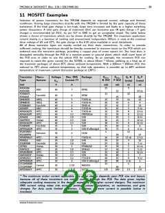
Figure 8.1 RSLP versus IDH
www.trinamic.com

 TRINAMIC [ TRINAMIC MOTION CONTROL GMBH & CO. KG. ]