TMC248-LA DATASHEET (Rev. 1.01 / 2013-MAR-26)
19
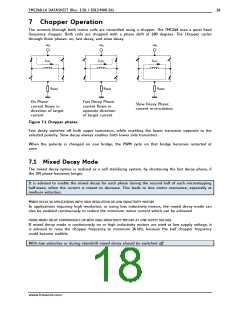
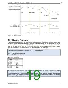
target current phase A
actual current phase A
on
slow decay
on
fast decay
slow decay
oscillator clock
resp. external clock
mixed decay disabled
mixed decay enabled
Figure 7.2 Chopper cycle
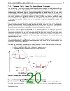
7.2 Chopper Frequency
The PWM oscillator frequency can be set by an external capacitor. The internal oscillator uses a 28k
resistor to charge / discharge the external capacitor to a trip voltage of 2/3 Vcc respectively 1/3 Vcc. It
can be overdriven using an external CMOS level square wave signal. Do not set the frequency higher
than 100 kHz and do not leave the OSC terminal open! The two bridges are chopped with a phase
shift of 180 degrees at the positive and at the negative edge of the clock signal.
ꢄ
The PWM oscillator frequency is calculated as:
ꢀꢁꢂ
ꢃ ꢅꢆꢇꢈꢉꢊꢉꢋ
ꢉꢏꢐꢑꢒ
ꢌꢍꢎ
fOSC:
COSC:
PWM oscillator frequency
Oscillator capacitor in nF
OSCILLATOR FREQUENCIES
fOSC typ.
COSC
16.7kHz
20.8kHz
25.0kHz
30.5kHz
36.8kHz
44.6kHz
1.5nF
1.2nF
1.0nF
820pF
680pF
560pF
An unnecessary high frequency leads to high switching losses in the power transistors and in the
motor.
For most applications a chopper frequency slightly above audible range is sufficient. When audible
noise occurs in an application, especially with mixed decay continuously enabled, the chopper
frequency should be two times the audible range.
www.trinamic.com

 TRINAMIC [ TRINAMIC MOTION CONTROL GMBH & CO. KG. ]