TMC248-LA DATASHEET (Rev. 1.01 / 2013-MAR-26)
16
6 Current Setting
6.1 Sense Resistor for Current Setting
Choose an appropriate sense resistor RS for setting the desired motor current.
Basic information:
-
The maximum motor current is reached, when the coil current setting is programmed to
1111.
-
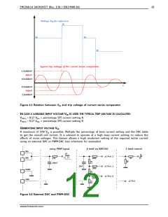
This results in a current sense trip voltage of 0.34V if the internal reference or a reference
voltage of 2V is used. (Refer to chapter 4.3 for more information about current setting in
SPI mode.)
-
The current sense resistor of bridge A, B is calculated as:
RSENSE = VTRIP / Imax
RSENSE Current sense resistor of bridge A, B
VTRIP
Programmed trip voltage of the current sense comparators
Desired maximum coil current
Mode of operation
Maximum motor current
Operation in fullstep mode
Operation in microstep mode
The maximum motor current is specified by the manufacturer.
Multiply the value for fullstep mode by 1.41 for the maximum
current Imax.
EXAMPLE FOR TYPICAL APPLICATION
RSENSE = 0.34V / Imax
POSSIBLE SENSE RESISTOR SETTINGS
RS
Imax
723mA
0.47
0.33
0.22
0.15
0.10
1030mA
1545mA
2267mA
3400mA
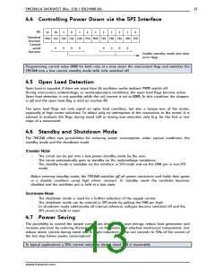
6.2 Resistor RSH for High Side Overcurrent Detection
The TMC248 detects an overcurrent to ground, when the voltage between VS (supply voltage) and VT
(threshold voltage) exceeds 150mV. The high side overcurrent detection resistor should be chosen in a
way that 100mV voltage drop are not exceeded between VS and VT, when both coils draw the
maximum current. In a microstep application, this is the case when sine and cosine wave have their
highest sum, i.e. at 45 degrees. This corresponds to 1.41 times the maximum current setting for one
coil. In a fullstep application this is adequate to the double coil current.
IN A MICROSTEP APPLICATION:
RSH = 0.1V / (1.41 Imax)
IN A FULLSTEP APPLICATION:
RSH = 0.1V / (2 Imax)
RSH:
Imax:
High side overcurrent detection resistor
Maximum coil current
If higher resistance values should be used, a voltage divider in the range of 10 to 100 can be used
for VT. This might also be desired to limit the peak short to GND current, as described in the
following chapter.
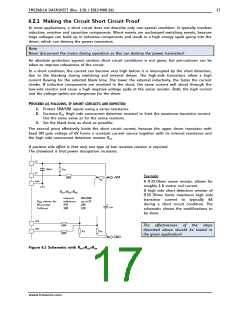
A careful PCB layout is required for the sense resistor traces and for the RSH traces.
www.trinamic.com

 TRINAMIC [ TRINAMIC MOTION CONTROL GMBH & CO. KG. ]