TMC248-LA DATASHEET (Rev. 1.01 / 2013-MAR-26)
15
5 Classical Non-SPI Control Mode (Standalone Mode)
The driver can be controlled by analog current control signals and digital phase signals.
Proceed as follows:
-
Tie pin SPE to GND for enabling non-SPI mode. In non-SPI mode the SPI interface is disabled
and the SPI input pins have alternate functions.
-
The internal DACs are forced to 1111.
5.1 Pin Functions in Standalone Mode
Pin
Standalone mode name Function in standalone mode
SPE
ANN
SCK
SDI
CSN
SDO
(GND)
MDAN
MDBN
PHA
PHB
ERR
Tie to GND to enable standalone mode
Enable mixed decay for bridge A (low = enable)
Enable mixed decay for bridge B (low = enable)
Polarity bridge A (low = current flow from output OA1 to OA2)
Polarity bridge B (low = current flow from output OB1 to OB2)
Error output (high = overcurrent on any bridge, or over
temperature). In this mode, the pin is never tri-stated.
Standby mode (high active), high causes a low power mode of the
device. Setting this pin high also resets all error conditions.
Current control for bridge A, resp. bridge B. Refer to AGND. The
sense resistor trip voltage is 0.34V when the input voltage is 2.0V.
Maximum input voltage is 3.0V.
ENN
ENN
INA,
INB
INA,
INB
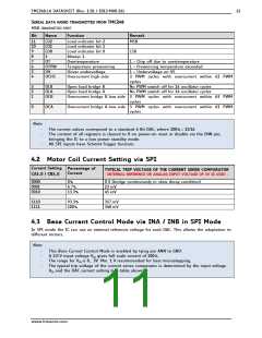
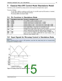
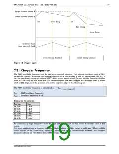
5.2 Input Signals for Microstep Control in Standalone Mode
Attention:
When transferring these waves to SPI operation, note that the mixed decay bits are inverted when
compared to standalone mode.
INA
INB
90°
180°
270°
360°
PHA
(SDI)
PHB
(CSN)
MDAN
(ANN)
MDBN
(SCK)
Use dotted line to improve
performance at medium velocities
Figure 5.1 Analog control for standalone mode
www.trinamic.com

 TRINAMIC [ TRINAMIC MOTION CONTROL GMBH & CO. KG. ]