UCD90320
ZHCSFI3B –AUGUST 2016–REVISED MAY 2019
www.ti.com.cn
•
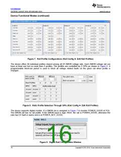
If rail voltage is monitored by an AMON pin, the Power Good status is solely determined by Power Good On
and Power Good Off thresholds as shown in Figure 6. A rail is given Power Good status if its rail voltage is
above the Power Good On threshold. Otherwise, the rail is given Not Power Good status if the rail voltage is
below the Power Good Off threshold. The rail remains in the current status if its voltage is neither above
Power Good On nor below Power Good Off thresholds.
•
If rail voltage is not monitored by a AMON or DMON pin, the Power Good status is determined by the turn-
ON and turn-OFF eligibility of the rail. A rail is immediately given Power Good status when the rail meets all
the turn-on conditions set by the user, such as On and Off Config, dependencies and delays. Similarly, a rail
is immediately given Not Power Good status when the rail meets all the turn-off conditions set by the user.
The behavior is the same regardless whether a physical EN pin is assigned to the rail.
The Power Good status is not affected by any warnings and faults unless the fault response is to turn OFF the
rail.
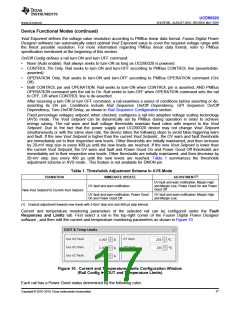
UV fault and warn notification is ignored when a rail is off. UV fault and warn notification is also ignored during
start up until the rail enters Power Good status for the first time. This mechanism avoids false-triggering UV fault
and warn notification when the rail voltage is expected to be below UV thresholds.
A Graceful Shutdown feature is enabled by checking the Configured as VIN Monitor checkbox. When enabled,
the rail is configured to monitor VIN. When VIN drops below Power Good Off threshold, the device ignores any
UV fault and warn notifications on any other rail.
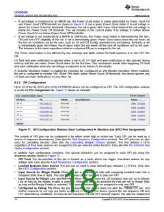
8.4.2 GPI Configuration
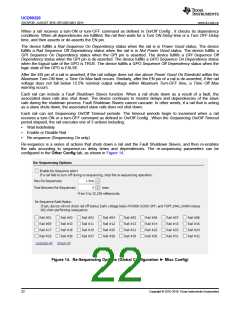
Up to 32 of the 84 GPIO pins of the UCD90320 device can be configured as GPI. The GPI configuration window
is under the Pin Assignment tab. Figure 11 shows an example.
Figure 11. GPI Configuration Window (Hard Configuration ► Monitors and GPIO Pins Assignment)
The polarity of GPI pins can be configured to be either active high or active low. Each GPI can be used as a
source of sequence dependency. (See also the Rail Sequence Configuration section). The GPI pins can be also
used for cascading function. (See also the Cascading Multiple Devices section). The first defined 3 GPIs
regardless of their main purpose are assigned to the pin selected states function. (See also the Pin Selected Rail
States Configuration section).
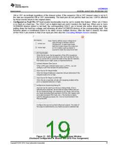
In addition hard configuration functions, four special behaviors can be assigned to each GPI pin using the
dropdown window shown in Figure 12:
•
•
•
•
GPI Fault The de-assertion of this pin is treated as a fault, which can trigger shut-down actions for any
voltage rails. (See also the Fault Responses Configuration section).
Latched Statuses Clear Source This pin can be used to clear latched-type statuses (_LATCH). (See also
the GPO Configuration section).
Input Source for Margin Enable When this pin is asserted, all rails with margining enabled enter into a
margined state (low or high). This special behavior can be assigned to only one GPI.
Input Source for Margin Low and Not-High When this pin is asserted, all margined rails are set to Margin
Low as long as the Margin Enable is asserted. When this pin is de-asserted the rails are set to Margin High
as long as the Margin Enable is asserted. This special behavior can be assigned to only one GPI.
•
Configured as Debug Pin When the pin is asserted, the device does not alert the PMBALERT pin, and
neither responds to, nor logs any faults as defined in Table 2. The device ignores the rail sequence ON and
OFF dependency conditions. As soon as the sequence ON and OFF timeout expires, the rails are sequenced
18
Copyright © 2016–2019, Texas Instruments Incorporated

 TI [ TEXAS INSTRUMENTS ]