UCD90320
www.ti.com.cn
ZHCSFI3B –AUGUST 2016–REVISED MAY 2019
Device Functional Modes (continued)
Vout Exponent defines the voltage value resolution according to PMBus linear data format. Fusion Digital Power
Designer software can automatically select optimal Vout Exponent value to cover the required voltage range with
the finest possible resolution. For more information regarding PMBus linear data format, refer to PMBus
specification mentioned at the beginning of this section.
On/Off Config defines a rail turn-ON and turn-OFF command:
•
•
None (Auto enable). Rail always seeks to turn-ON as long as UCD90320 is powered.
CONTROL Pin Only. Rail seeks to turn-ON and turn-OFF according to PMBus CONTROL line (asserted/de-
asserted).
•
•
OPERATION Only. Rail seeks to turn-ON and turn-OFF according to PMBus OPERATION command (On/
Off).
Both CONTROL pin and OPERATION. Rail seeks to turn-ON when CONTROL pin is asserted, AND PMBus
OPERATION command sets the rail to On. Rail seeks to turn-OFF when OPERATION command sets the rail
to OFF, OR when CONTROL line is de-asserted.
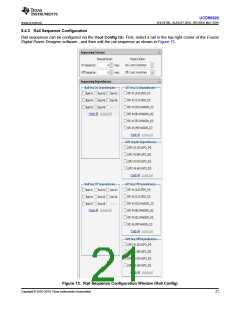
After receiving a turn ON or turn OFF command, a rail examines a series of conditions before asserting or de-
asserting its EN pin. Conditions include Rail Sequence On/Off Dependency, GPI Sequence On/Off
Dependency, Turn-On/Off Delay, as shown in Rail Sequence Configuration section.
Fixed percentage voltages setpoint, when checked, configures a rail into adaptive voltage scaling technology
(AVS) mode. The Vout Setpoint can be dynamically set by PMBus during operation in order to achieve
energy saving. The rail warn and fault voltage thresholds maintain fixed ratios with respect to the Vout
Setpoint. Due to the fact that the power supply and UCD90320 device may not change Vout Setpoint
simultaneously or with the same slew rate, the device takes the following steps to avoid false-triggering warn
and fault. If the new Vout Setpoint is higher than the current Vout Setpoint , the OV warn and fault thresholds
are immediately set to their respective new levels. Other thresholds are initially maintained, and then increase
by 20-mV step size in every 400 µs until the new levels are reached. If the new Vout Setpoint is lower than
the current Vout Setpoint, the UV warn and fault and Power Good On and Power Good Off thresholds are
immediately set to their respective new levels. Other thresholds are initially maintained, and then decrease by
20-mV step size every 400 µs until the new levels are reached. Table 1 summarizes the thresholds
adjustment scheme in AVS mode.. This feature is not available for DMON pin.
Table 1. Thresholds Adjustment Scheme in AVS Mode
TRANSITION
IMMEDIATE UPDATE
ADJUSTMENT(1)
UV fault and warn notification, Margin High
and Margin Low, Power Good On and Power
Good Off
OV fault and warn notification
New Vout Setpoint to Current Vout Setpoint
UV fault and warn notification, Power Good
On and Power Good Off
OV fault and warn notification, Margin High
and Margin Low,
(1) Gradual adjustment towards new levels with 2-0mV step size and 400-µs step interval
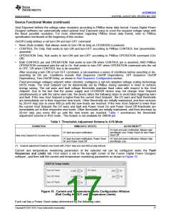
Current and temperature monitoring parameters of the selected rail can be configured under the Fault
Responses and Limits tab. First select a rail in the top-right corner of the Fusion Digital Power Designer
software , and then edit the current and temperature monitoring parameters as shown in Figure 10.
Figure 10. Current and Temperature Limits Configuration Window
(Rail Config ► IOUT and Temperature Limits)
Each rail has a Power Good status determined by the following rules.
Copyright © 2016–2019, Texas Instruments Incorporated
17

 TI [ TEXAS INSTRUMENTS ]