ꢀꢁꢁ ꢂ ꢃꢄ ꢅ ꢆ ꢀꢁꢁ ꢂ ꢃꢄ ꢇ ꢆ ꢀ ꢁꢁ ꢂꢃ ꢄꢄ
ꢀꢁꢁ ꢈ ꢃꢄ ꢅ ꢆ ꢀꢁꢁ ꢈ ꢃꢄ ꢇ ꢆ ꢀ ꢁꢁ ꢈꢃ ꢄꢄ
SLUS499A – NOVEMBER 2001 – REVISED JANUARY 2002
description (continued)
SHUTDOWN
C
R
OPEN
OPEN
VDD
1
2
OPEN/SD VDD
UCC3975
8
PIEZO
XFMR
OSC
R
HV
OUTP
7
6
R
C
OSC
OSC
RANGE
N
3
4
COMP
FB
OUTN
GND
R
C
CNT
FB
5
V
CNT
R
FB
D
FB
CCFL
R
CS
UDG–01098
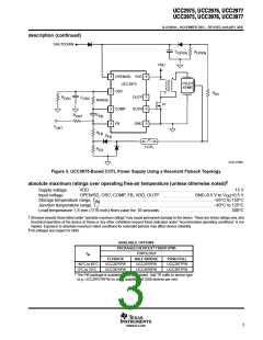
Figure 3. UCC3975-Based CCFL Power Supply Using a Resonant Flyback Topology
†
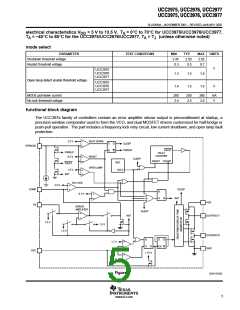
absolute maximum ratings over operating free-air temperature (unless otherwise noted)
Supply voltage
Input voltage
VDD . . . . . . . . . . . . . . . . . . . . . . . . . . . . . . . . . . . . . . . . . . . . . . . . . . . . . . . . . . . . . . . . . . 15 V
OPEN/SD, OSC, COMP, FB, VDD, OUTP . . . . . . . . . . . . . . GND–0.5 V to V +0.5 V
DD
Storage temperature range, T . . . . . . . . . . . . . . . . . . . . . . . . . . . . . . . . . . . . . . . . . . . . . . . . . . . . –65°C to 150°C
Junction temperature range, T . . . . . . . . . . . . . . . . . . . . . . . . . . . . . . . . . . . . . . . . . . . . . . . . . . . . –40°C to 125°C
Lead temperature 1,6 mm (1/16 inch) from case for 10 seconds . . . . . . . . . . . . . . . . . . . . . . . . . . . . . . . . 300°C
stg
J
†
§
Stresses beyond those listed under “absolute maximum ratings” may cause permanent damage to the device. These are stress ratings only, and
functional operation of the device at these or any other conditions beyond those indicated under “recommended operating conditions” is not
implied. Exposure to absolute-maximum-rated conditions for extended periods may affect device reliability.
All voltages are respect to GND.
AVAILABLE OPTIONS
†
PACKAGED DEVICES TSSOP (PW)
TOPOLOGY
T
A
FLYBACK
HALF-BRIDGE
UCC2976PW
UCC3976PW
PUSH-PULL
–40°C to 85°C
0°C to 70°C
UCC2975PW
UCC3975PW
UCC2977PW
UCC3977PW
†
The PW package is available taped and reeled. Add TR suffix to device type
(e.g. UCC2975TRPW) to order quantities of 2500 devices per reel.
3
www.ti.com

 TI [ TEXAS INSTRUMENTS ]