ꢀ ꢁꢁꢂ ꢃ ꢄ ꢅ ꢆ ꢀ ꢁ ꢁꢂ ꢃ ꢄ ꢇ ꢆ ꢀꢁ ꢁꢂ ꢃ ꢄ ꢄ
ꢀ ꢁꢁꢈ ꢃ ꢄ ꢅ ꢆ ꢀ ꢁ ꢁꢈ ꢃ ꢄ ꢇ ꢆ ꢀꢁ ꢁꢈ ꢃ ꢄ ꢄ
SLUS499A – NOVEMBER 2001 – REVISED JANUARY 2002
description (continued)
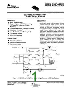
A half-bridge PZT converter, using the UCC3976 is shown in Figure 1. External P- and N-channel MOSFETs
are driven out of phase at a fixed 50% duty cycle with anti-cross conduction circuitry provided by the controller.
The half-bridge topology uses only a single magnetic component (LRES) reducing board area. As explained
in the applications section of this datasheet, regulation of lamp current is achieved by controlling the operating
frequency of the system.
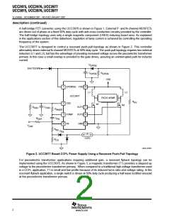
The UCC3977 is designed to control a resonant push-pull topology as shown in Figure 2. This controller
alternately drives external N-channel MOSFETs at 50% duty cycle. The push-pull topology requires two external
inductors (L1 and L2), but has the advantage of providing increased voltage across the piezoelectric transformer
primary. In this case a small overlap is provided to the gate drives, assuring an uninterrupted path for inductor
current.
D
OPEN
SHUTDOWN
C
R
OPEN
OPEN
VDD
1
2
OPEN/SD VDD
UCC3977
8
L1
L2
PIEZO XFMR
R
HV
OSC
N1
N2
OUT1
7
6
R
C
OSC
OSC
R
ANGE
3
4
COMP
FB
OUT2
GND
R
C
FB
CNT
5
V
CNT
R
FB
D
FB
CCFL
R
CS
UDG–01097
Figure 2. UCC3977 Based CCFL Power Supply Using a Resonant Push-Pull Topology
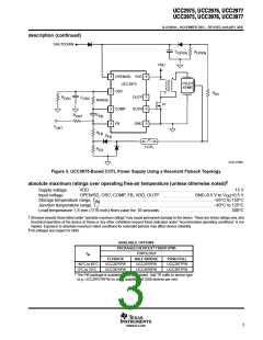
For piezoelectric transformer applications requiring additional gain, a resonant flyback topology can be
implemented using the UCC3975. As shown in Figure 3, a magnetic transformer (T1) provides a stepped up
voltage to the piezoelectric transformer primary. When compared to a traditional high-voltage transformer used
in a CCFL application, T1 is small and low profile because of its reduced turns ratio and voltage rating. In the
resonant flyback application, a single switch is driven at 50% duty cycle producing a half wave rectified sinusoid
at the piezoelectric transformer primary.
2
www.ti.com

 TI [ TEXAS INSTRUMENTS ]