ꢀꢁꢁ ꢂ ꢃꢄ ꢅ ꢆ ꢀꢁꢁ ꢂ ꢃꢄ ꢃ ꢆ ꢀꢁꢁ ꢇ ꢃꢄ ꢅ ꢆ ꢀ ꢁꢁ ꢇꢃ ꢄꢃ
ꢈꢉ ꢁꢊꢋ ꢌ ꢍꢋ ꢎ ꢏꢐ ꢑꢒꢁꢓꢋ ꢐ ꢍꢐ ꢏꢐꢏꢔ ꢀꢕ ꢒꢓꢋ ꢐ
ꢖ
SLUS395J - FEBRUARY 2000 - REVISED MARCH 2009
APPLICATION INFORMATION
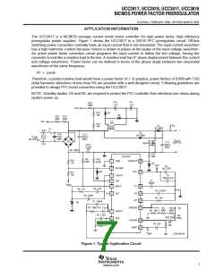
The UCC3817 is a BiCMOS average current mode boost controller for high power factor, high efficiency
preregulator power supplies. Figure 1 shows the UCC3817 in a 250-W PFC preregulator circuit. Off-line
switching power converters normally have an input current that is not sinusoidal. The input current waveform
has a high harmonic content because current is drawn in pulses at the peaks of the input voltage waveform.
An active power factor correction circuit programs the input current to follow the line voltage, forcing the
converter to look like a resistive load to the line. A resistive load has 0° phase displacement between the current
and voltage waveforms. Power factor can be defined in terms of the phase angle between two sinusoidal
waveforms of the same frequency:
PF + cosQ
Therefore, a purely resistive load would have a power factor of 1. In practice, power factors of 0.999 with THD
(total harmonic distortion) of less than 3% are possible with a well-designed circuit. Following guidelines are
provided to design PFC boost converters using the UCC3817.
NOTE: Schottky diodes, D5 and D6, are required to protect the PFC controller from electrical over stress during
system power up.
C10
1 µ F
C11
1 µF
R16
100Ω
VCC
R15
24k
D7
D8
R21
R13
383k 383k
L1
IAC
1mH
R18
24k
V
D1
8A, 600V
O
F1
AC2
+
D2
6A, 600V
C14
C13
V
F
F
µ
µ
1.5
400V
0.47
600V
LINE
85−270 V
AC
V
Q1
IRFP450
OUT
D3
C12
220µF
450V
385V−DC
AC1
R14
0.25
Ω
3W
6A 600V
−
R17
20Ω
UCC3817
R9
4.02k
R10
4.02k
R12
2k
1
2
GND
DRVOUT 16
D4
VCC
C3
PKLIMIT
1µF CER
D5
VCC 15
R11
10k
3
4
5
CAOUT
CAI
C2
100
µ F AI EI
C1
560pF
V
REF
MOUT
CT 14
SS 13
C9 1.2nF
R8 12k
µ
C4 0.01 F
6
IAC
C8 270pF
R1 12k
RT 12
C7 150nF
D6
µ
R7 100k C15 2.2
F
VSENSE 11
V
R2
499k
R19
499k
O
R3 20k
7
8
VAOUT
VFF
C6 2.2µF
R4
249k
R20 274k
OVP/EN 10
R5
10k
R6 30k
µF
C5 1
VREF
9
V
UDG-98183
REF
Figure 1. Typical Application Circuit
7
www.ti.com

 TI [ TEXAS INSTRUMENTS ]