ꢀ ꢁꢁꢂ ꢃ ꢄ ꢅ ꢆ ꢀ ꢁꢁ ꢂ ꢃꢄ ꢃ ꢆ ꢀꢁ ꢁꢇ ꢃ ꢄ ꢅ ꢆ ꢀꢁ ꢁꢇ ꢃ ꢄ ꢃ
ꢈ ꢉꢁꢊ ꢋꢌ ꢍꢋꢎ ꢏꢐ ꢑꢒꢁ ꢓꢋ ꢐ ꢍ ꢐꢏ ꢐꢏ ꢔꢀ ꢕꢒꢓꢋ ꢐ
ꢖ
SLUS395J - FEBRUARY 2000 - REVISED MARCH 2009
APPLICATION INFORMATION
multiplier (continued)
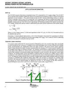
The I
signal is obtained through a high-value resistor connected between the rectified ac line and the IAC
IAC
pin of the UCC3817/18. This resistor (R
UCC3817/18 the maximum I
) is sized to give the maximum I
current at high line. For the
IAC
IAC
current is about 500 µA. A higher current than this can drive the multiplier out
IAC
of its linear range. A smaller current level is functional, but noise can become an issue, especially at low input
line. Assuming a universal line operation of 85 V to 265 V gives a R value of 750 kΩ. Because of
RMS
RMS
IAC
voltage rating constraints of standard 1/4-W resistor, use a combination of lower value resistors connected in
series to give the required resistance and distribute the high voltage amongst the resistors. For this design
example two 383-kΩ resistors were used in series.
The current into the IAC pin is mirrored internally to the VFF pin where it is filtered to produce a voltage feed
forward signal proportional to line voltage. The VFF voltage is used to keep the power stage gain constant; and
to provid input power limiting. Please refer to Texas Instruments application note SLUA196 for detailed
explanation on how the VFF pin provides power limiting. The following equation can be used to size the VFF
resistor (R
) to provide power limiting where V
is the minimum RMS input voltage and R
is the total
VFF
IN(min)
IAC
resistance connected between the IAC pin and the rectified line voltage.
1.4 V
R
+
[ 30 kW
VFF
V
0.9
IN(min)
2 R
IAC
Because the VFF voltage is generated from line voltage it needs to be adequately filtered to reduce total
harmonic distortion caused by the 120 Hz rectified line voltage. Refer to Unitrode Power Supply Design
Seminar, SEM−700 Topic 7, [Optimizing the Design of a High Power Factor Preregulator.] A single pole filter
was adequate for this design. Assuming that an allocation of 1.5% total harmonic distortion from this input is
allowed, and that the second harmonic ripple is 66% of the input ac line voltage, the amount of attenuation
required by this filter is:
1.5 %
+ 0.022
66 %
With a ripple frequency (f ) of 120 Hz and an attenuation of 0.022 requires that the pole of the filter (f ) be placed
R
P
at:
f
+ 120 Hz 0.022 [ 2.6 Hz
P
The following equation can be used to select the filter capacitor (C
filter.
) required to produce the desired low pass
VFF
1
C
+
[ 2.2 mF
VFF
2 p R
f
VFF
P
The R
resistor is sized to match the maximum current through the sense resistor to the maximum multiplier
MOUT
current. The maximum multiplier current, or I
, can be determined by the equation:
MOUT(max)
ǒVVAOUT(max) * 1VǓ
I
@V
IAC
IN(min)
I
+
MOUT(max)
2
K V
VFF
(min)
10
www.ti.com

 TI [ TEXAS INSTRUMENTS ]