ꢀꢁꢁ ꢂ ꢃꢄ ꢅ ꢆ ꢀꢁꢁ ꢂ ꢃꢄ ꢃ ꢆ ꢀꢁꢁ ꢇ ꢃꢄ ꢅ ꢆ ꢀ ꢁꢁ ꢇꢃ ꢄꢃ
ꢈꢉ ꢁꢊꢋ ꢌ ꢍꢋ ꢎ ꢏꢐ ꢑꢒꢁꢓꢋ ꢐ ꢍꢐ ꢏꢐꢏꢔ ꢀꢕ ꢒꢓꢋ ꢐ
ꢖ
SLUS395J - FEBRUARY 2000 - REVISED MARCH 2009
APPLICATION INFORMATION
multiplier (continued)
I
for this design is approximately 315 µA. The R
resistor can then be determined by:
MOUT(max)
MOUT
V
RSENSE
+
R
MOUT
I
MOUT(max)
In this example V
was selected to give a dynamic operating range of 1.25 V, which gives an R
of
RSENSE
MOUT
roughly 3.91 kΩ.
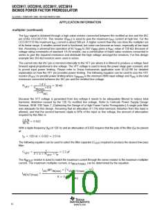
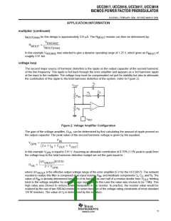
voltage loop
The second major source of harmonic distortion is the ripple on the output capacitor at the second harmonic
of the line frequency. This ripple is fed back through the error amplifier and appears as a 3rd harmonic ripple
at the input to the multiplier. The voltage loop must be compensated not just for stability but also to attenuate
the contribution of this ripple to the total harmonic distortion of the system. (refer to Figure 2).
C
f
V
OUT
C
R
Z
f
R
IN
−
+
R
D
V
REF
Figure 2. Voltage Amplifier Configuration
The gain of the voltage amplifier, G , can be determined by first calculating the amount of ripple present on
VA
the output capacitor. The peak value of the second harmonic voltage is given by the equation:
P
IN
V
+ ǒ2 p f
OUTǓ
OPK
C
V
R
OUT
In this example V
is equal to 3.91 V. Assuming an allowable contribution of 0.75% (1.5% peak to peak) from
OPK
the voltage loop to the total harmonic distortion budget we set the gain equal to:
ǒDV
Ǔ(
)
0.015
VAOUT
2 V
G
+
VA
OPK
where ∆V
is the effective output voltage range of the error amplifier (5 V for the UCC3817). The network
VAOUT
needed to realize this filter is comprised of an input resistor, R , and feedback components C , C , and R . The
IN
f
Z
f
value of R is already determined because of its function as one half of a resistor divider from V
feeding
IN
OUT
back to the voltage amplifier for output voltage regulation. In this case the value was chosen to be 1 MΩ. This
high value was chosen to reduce power dissipation in the resistor. In practice, the resistor value would be
realized by the use of two 500-kΩ resistors in series because of the voltage rating constraints of most standard
1/4-W resistors. The value of C is determined by the equation:
f
11
www.ti.com

 TI [ TEXAS INSTRUMENTS ]