UCC28951
www.ti.com.cn
ZHCSIQ7A –AUGUST 2018 –REVISED DECEMBER 2021
7.4 Device Functional Modes
The UCC28951 offers many operational modes. These modes are described in detail in 节7.3.
• Current mode1. The UCC28951 controller operates in current mode control when the RSUM pin is connected
to GND through a resistor (RSUM) . The resistor sets the amount of slope compensation.
• Voltage mode1. The controller operates in voltage mode control when the RSUM pin is connected to VREF
through a resistor (RSUM). The chosen resistor value gives the correct amount of slope compensation for
operation in current limit mode (cycle-by-cycle current limit).
• DCM mode. The controller enters DCM mode when the signal at the CS pin falls below the level set by the
resistor at the DCM pin. The SR drives (OUTE and OUTF) turn off and secondary rectification occurs through
the body diodes of the SRs.
• Burst mode. The controller enters burst mode when the pulse width demanded by the feedback signal falls
below the width set by the resistor at the TMIN pin.
• Leader mode. This is the default operation mode of the controller and is used when there is only one
UCC28951 controller in the system. Connect the timing resistor (RT) from the RT pin to VREF. In a system
with more than one UCC28951 controller, configure one as the leader and the others as followers1.
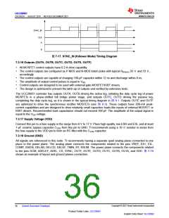
• Follower mode. The follower controller operates with a 90° phase shift relative to the leader (providing their
SYNC pins are tied together). Connect the timing resistor (RT) from the RT pin to GND and connect an 825-
kΩ±5% resistor from the SS/EN pin to GND1.
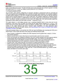
• Synchronized mode. When a UC28950 controller is configured as a follower, its SYNC pin is used as an
input. The follower synchronizes its internal oscillator at 90° to the signal at its SYNC pin. The application
note, Synchronizing Three or More UCC28950 Phase-Shifted, Full-Bridge Controllers, discusses how
multiple follower controllers may be synchronized to a single leader oscillator.
• Hiccup mode. This mode provides overload protection to the power circuit. The UCC28951 controller stops
switching after a certain time in current limit. It starts again (soft-start) after a delay time. The user can control
the time spent in current limit before switching is stopped and the delay time before the soft start happens.
• Current-limit mode. The UCC28951c ontroller provides cycle-by-cycle current limiting when the signal at the
CS pin reaches 2 V.
• Latch-off mode. Connect a resistor between the SS pin and VREF. The UCC28951 controller then latches off
when the controller enterscurrent-limit mode. 1
1
Current mode control and voltage mode control are mutually exclusive as are leader and follower modes.
Copyright © 2023 Texas Instruments Incorporated
English Data Sheet: SLUSDB2
38
Submit Document Feedback
Product Folder Links: UCC28951

 TI [ TEXAS INSTRUMENTS ]