UCC28951
www.ti.com.cn
ZHCSIQ7A –AUGUST 2018 –REVISED DECEMBER 2021
8 Application and Implementation
备注
以下应用部分中的信息不属于 TI 元件规格,TI 不担保其准确性和完整性。TI 的客户负责确定元件是否
适合其用途,以及验证和测试其设计实现以确认系统功能。
8.1 Application Information
The high efficiency of a phase-shifted full-bridge DC-DC converter using the UCC28951 is achieved by using
synchronous rectification, a control algorithm providing ZVS condition over the entire load current range,
accurate adaptive timing of the control signals between primary and secondary FETs and special operating
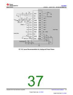
modes at light load. A simplified electrical diagram of this converter is shown in 图 8-3. The UCC28951controller
is located on the secondary side of converter, although it could be placed on the primary side as well. The
secondary side lication allows easy power system level communication and better handling of some transient
conditions that require fast direct control of the synchronous rectifier MOSFETs. The power stage includes
primary side MOSFETs, QA, QB, QC, QD and secondary side synchronous rectifier MOSFETs, QE and QF. For
example, for the 12-V output converters in server power supplies use of the center-tapped rectifier scheme with
L-C output filter is a popular choice.
To maintain high efficiency at different output power conditions, the converter operates in synchronous
rectification mode at mid and high output power levels, transitioning to diode rectifier mode at light load and then
into burst mode as the output power becomes even lower. All of these transitions are based on current sensing
on the primary side using a current sense transformer in this specific case.
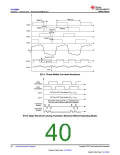
The major waveforms of the phase-shifted converter during normal operation are shown in 图 8-1. The upper six
waveforms in 图 8-1 show the output drive signals of the controller. In normal mode, the outputs OUTE and
OUTF overlap during the part of the switching cycle when both rectifier MOSFETs are conducting and the
windings of the power transformer are shorted. Current, IPR, is the current flowing through the primary winding of
the power transformer. The bottom four waveforms show the drain-source voltages of rectifier MOSFETs, VDS_QE
and VDS_QF, the voltage at the output inductor, V LOUT, and the current through the output inductor, I LOUT
.
Proper timing between the primary switches and synchronous rectifier MOSFETs is critical to achieve highest
efficiency and reliable operation in this mode. The controller adjusts the turn OFF timing of the rectifier
MOSFETs as a function of load current to ensure minimum conduction time and reverse recovery losses of their
internal body diodes.
ZVS is an important feature of relatively high input voltage converters in reducing switching losses associated
with the internal parasitic capacitances of power switches and transformers. The controller ensures ZVS
conditions over the entire load current range by adjusting the delay time between the primary MOSFETs
switching in the same leg in accordance to the load variation. The controller also limits the minimum ON-time
pulse applied to the power transformer at light load, allowing the storage of sufficient energy in the inductive
components of the power stage for the ZVS transition.
As the load current reduces from full load down to the no-load condition, the controller selects the most efficient
power saving mode by moving from the normal operation mode to the discontinuous-current diode-rectification
mode and, eventually, at very light-load and at no-load condition, to the burst mode. These modes and related
output signals, OUTE, OUTF, driving the rectifier MOSFETs, are shown in 图8-2.
Copyright © 2023 Texas Instruments Incorporated
Submit Document Feedback
39
Product Folder Links: UCC28951
English Data Sheet: SLUSDB2

 TI [ TEXAS INSTRUMENTS ]