UCC28070-Q1
SLUSA71A –JULY 2010–REVISED JUNE 2011
www.ti.com
Current Synthesizer
One of the most prominent innovations in the UCC28070 design is the current synthesizer circuitry that
synchronously monitors the instantaneous inductor current through a combination of on-time sampling and
off-time down-slope emulation.
During the on-time of the GDA and GDB outputs, the inductor current is recorded at the CSA and CSB pins
respectively via the current transformer network in each output phase. Meanwhile, the continuous monitoring of
the input and output voltage via the VINAC and VSENSE pins permits the UCC28070 to internally recreate the
inductor current's down-slope during each output's respective off-time. Through the selection of the RSYNTH
resistor (RSYN), based on the equation below, the internal response may be adjusted to accommodate the wide
range of inductances expected across the wide array of applications.
During inrush surge events at power-up and ac drop-out recovery, VSENSE < VINAC, so the synthesized down
slope becomes zero. In this case, the synthesized inductor current will remain above the IMO reference and the
current loop drives the duty cycle to zero. This avoids excessive stress on the MOSFETS during the surge event.
Once VINAC falls below VSENSE the duty cycle increases until steady-state operation resumes.
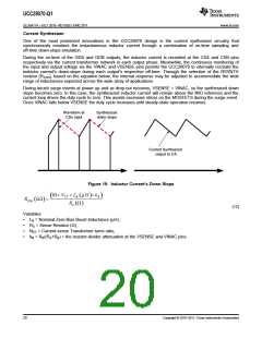
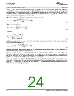
Waveform at
CSx input
Synthesized
down-slope
Current Synthesizer
output to CA
Figure 19. Inductor Current's Down Slope
10´ N ´ L mH ´k
B ( )
(
)
CT
R
RSYN kW =
( )
R W
S ( )
(12)
Variables
•
•
•
•
LB = Nominal Zero-Bias Boost Inductance (μH),
RS = Sense Resistor (Ω),
NCT = Current-sense Transformer turns ratio,
kR = RB/(RA+RB) = the resistor-divider attenuation at the VSENSE and VINAC pins.
20
Copyright © 2010–2011, Texas Instruments Incorporated

 TI [ TEXAS INSTRUMENTS ]