UCC27523, UCC27524, UCC27525, UCC27526
www.ti.com
SLUSAQ3F –NOVEMBER 2011–REVISED MAY 2013
Enable Function
The enable function is an extremely beneficial feature in gate-driver devices especially for certain applications
such as synchronous rectification where the driver outputs disable in light-load conditions to prevent negative
current circulation and to improve light-load efficiency.
UCC27523/4/5 devices are provided with independent enable pins ENx for exclusive control of each driver-
channel operation. The enable pins are based on a non-inverting configuration (active-high operation). Thus
when ENx pins are driven high the drivers are enabled and when ENx pins are driven low the drivers are
disabled. Like the input pins, the enable pins are also based on a TTL and CMOS compatible input-threshold
logic that is independent of the supply voltage and are effectively controlled using logic signals from 3.3-V and 5-
V microcontrollers. The UCC2752X devices also feature tight control of the Enable-function threshold-voltage
levels which eases system design considerations and ensures stable operation across temperature (refer to
Figure 15). The ENx pins are internally pulled up to VDD using pullup resistors as a result of which the outputs of
the device are enabled in the default state. Hence the ENx pins are left floating or Not Connected (N/C) for
standard operation, where the enable feature is not needed. Essentially, this floating allows the UCC27523/4/5
devices to be pin-to-pin compatible with TI’s previous generation drivers UCC27323/4/5 respectively, where pins
#1, 8 are N/C pins. If the channel A and Channel B inputs and outputs are connected in parallel to increase the
driver current capacity, ENA and ENB are connected and driven together.
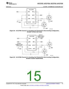
The UCC27526 device does not feature dedicated enable pins. However, as mentioned earlier, an
enable/disable function is easily implemented in UCC27526 using the unused input pin. When INx+ is pulled-
down to GND or INx- is pulled-down to VDD, the output is disabled. Thus INx+ pin is used like an enable pin that
is based on active high logic, while INx- is used like an enable pin that is based on active low logic.Note that
while the ENA, ENB pins in UCC27523/4/5 are allowed to be in floating condition during standard operation and
the outputs will be enabled, the INx+, INx- pins in UCC27526 are not allowed to be floating because this will
disable the outputs.
Copyright © 2011–2013, Texas Instruments Incorporated
Submit Documentation Feedback
19
Product Folder Links: UCC27523, UCC27524, UCC27525, UCC27526

 TI [ TEXAS INSTRUMENTS ]